What Is a Fiber Loopback Module? Types, Specs & How to Choose
A fiber loopback module is a compact passive optical device that routes a transmitted optical signal directly back into the receive channel of the same interface. It creates a controlled, self-contained optical path so engineers can verify a port or transceiver without a full end-to-end fiber link. Loopbacks are used every day for transceiver testing, port diagnostics, network troubleshooting, and burn-in testing across data centers, telecom networks, optical labs, and production lines.
This guide explains how a fiber loopback module works, the main connector and fiber types, the specifications that matter, how single mode compares to multimode, and a clear checklist for choosing the right part.
How a Fiber Loopback Module Works
A loopback module connects the transmit (TX) side of an optical interface back to its receive (RX) side. When the device under test emits an optical signal, the internal fiber routes that signal straight back into the receiver — letting you confirm the port and transceiver can send and receive correctly, in isolation from the rest of the network.
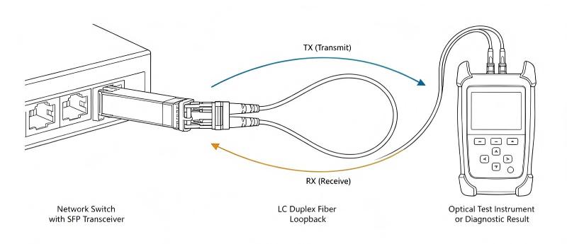
The transceiver transmits an optical signal on the TX channel
The loopback module's internal fiber carries it to the RX channel
The receiver detects the returned signal and reports link status
A pass confirms the local optics; a fail isolates the fault to that port
In a duplex LC or SC loopback, one internal fiber joins TX to RX. In an MTP®/MPO loopback, multiple transmit channels are looped back to their corresponding receive channels according to the required fiber count and polarity.
Common Applications
Optical transceiver testing — validate SFP, SFP+, SFP28, QSFP, QSFP28, QSFP-DD, and OSFP modules before deployment
Switch and router port diagnostics — confirm a port can transmit and receive to isolate hardware or contamination issues
Network troubleshooting — test the local port to eliminate fault points before checking remote devices
Burn-in testing — run optics continuously in manufacturing to catch unstable ports and early failures
Lab and production testing — repeatable, compact tooling for single-channel and high-density parallel testing
Main Types of Fiber Loopback Modules
Loopback modules are classified by connector type, fiber type, fiber count, and polish. Match the module to the interface of the device being tested.
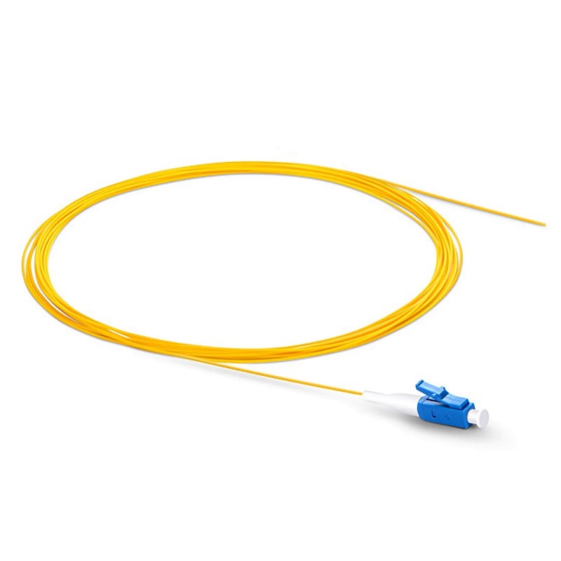
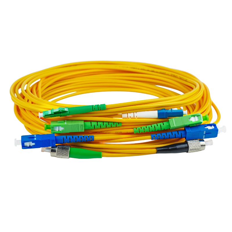
LC Fiber Loopback Module
The most common format for compact, high-density optics such as SFP, SFP+, and SFP28. Available in OS2 single mode (UPC/APC) and OM1–OM4 multimode.
SC Fiber Loopback Module
Used with switches, routers, media converters, test equipment, and legacy SC-interface devices. Available in OS2 single mode (UPC/APC) and OM1–OM4 multimode, with a secure push-pull mate.
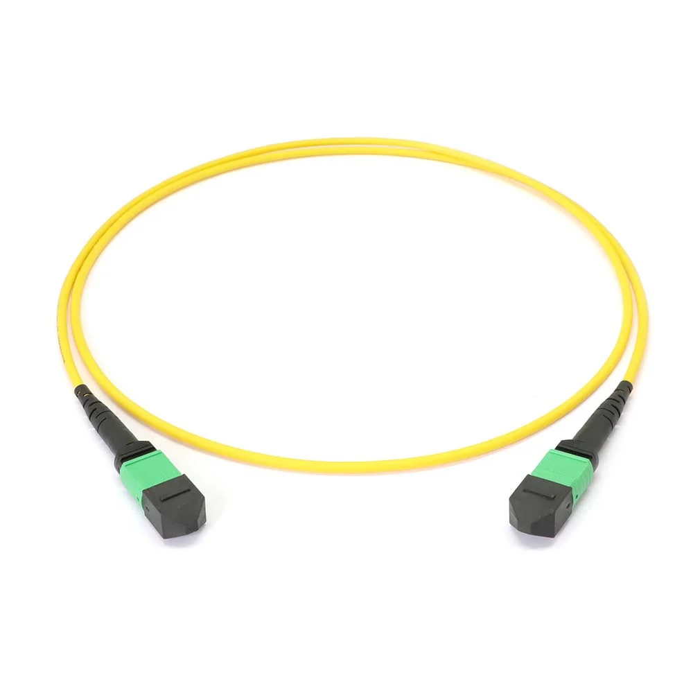
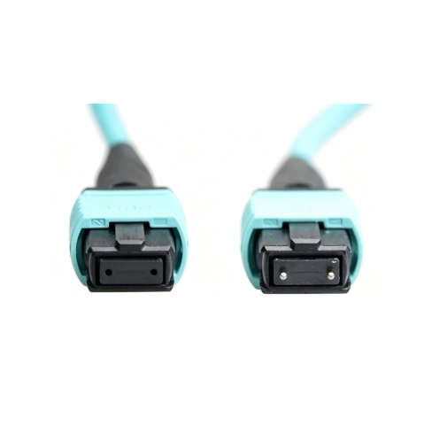
MTP®/MPO Fiber Loopback Module
Designed for high-density parallel interfaces — QSFP, QSFP28, QSFP-DD, OSFP, and 400G/800G optics. Loops multiple channels at once, in common fiber counts of 8, 12, 16, and 24. Fiber count, connector gender, key orientation, and polarity must be selected carefully to match the test setup.
LC vs SC vs MTP/MPO at a Glance
Type | Density | Channels Looped | Typical Interface |
|---|---|---|---|
LC | High (compact) | 1 duplex pair | SFP / SFP+ / SFP28 |
SC | Standard | 1 duplex pair | Switches, routers, legacy gear |
MTP/MPO | Very high (parallel) | 8 / 12 / 16 / 24 fibers | QSFP / QSFP-DD / OSFP, 400G/800G |
Single Mode vs Multimode Loopback Modules
Fiber type is one of the most important selection factors — the loopback must match the transceiver or equipment interface.
Parameter | Single Mode (OS2) | Multimode (OM3/OM4) |
|---|---|---|
Core/Cladding | 9/125 µm | 50/125 µm |
Wavelength | 1310 / 1550 nm | 850 nm (1300 nm) |
Typical Reach | Long-haul / backbone | Short-reach data center |
Polish Options | UPC / APC | UPC |
Common Use | Telecom, single-mode DC links | High-speed 850 nm systems |
OM1 (62.5/125 µm) and OM2 (50/125 µm) are mainly for legacy networks; OM3 and OM4 laser-optimized fiber dominate modern high-speed data center testing.
Typical Loopback Module Specifications
Parameter | Single Mode (OS2) | Multimode (OM3/OM4) |
|---|---|---|
Insertion Loss | ≤ 0.3 dB typ. | ≤ 0.3 dB typ. |
Return Loss | ≥ 50 dB (UPC) / ≥ 60 dB (APC) | ≥ 35 dB |
Operating Temp. | -40°C to +85°C | -40°C to +85°C |
Durability | ≥ 1000 matings | ≥ 1000 matings |
Fiber Counts (MPO) | 8 / 12 / 16 / 24 | 8 / 12 / 16 / 24 |
UPC vs APC: Which Polish Should You Choose?
For single mode LC and SC loopbacks, both polish types are available.
UPC — standard single-mode polish, suitable for most transceiver testing and troubleshooting
APC — angled polish that reduces back reflection; preferred where return loss control matters, such as PON and high-performance telecom systems
The rule is simple: match the polish of the equipment interface. Never mate UPC to APC — the differing end-face geometry causes poor performance and can damage the connectors.
Key Factors When Choosing a Loopback Module
Connector type — LC, SC, or MTP®/MPO
Fiber type — OS2 single mode, or OM1–OM4 multimode
Polish type — UPC or APC (match the interface)
Wavelength — 850, 1300, 1310, or 1550 nm
Fiber count — critical for MPO (8/12/16/24)
Polarity & connector gender — required for correct MPO channel mapping
Housing & labeling — helps fast identification in labs and production
For LC and SC loopbacks the selection is usually straightforward. For MPO, always confirm polarity, pin configuration, and fiber count before ordering.
Firsol Fiber Loopback Module Solutions
Firsol supplies fiber loopback modules for transceiver testing, network troubleshooting, equipment diagnostics, and burn-in applications, including:
LC and SC loopbacks in OS2 single mode (UPC/APC) and OM1–OM4 multimode
MTP®/MPO loopbacks in 8, 12, 16, and 24 fiber counts for parallel optics
Custom connector gender, polarity, housing color, and labeling
Whether you need a simple LC/UPC loopback for SFP testing or a high-density MPO loopback for 400G/800G diagnostics, Firsol delivers reliable solutions for lab, production, telecom, and data center environments.
Frequently Asked Questions
What does a fiber loopback module actually test?
It confirms that an optical port and transceiver can transmit and receive light correctly. It does not test the full network path — only the local optics up to the connector.
How do I pick the right MPO loopback?
Match the fiber count (8/12/16/24), fiber type (OS2 or OM3/OM4), connector gender, and polarity to the transceiver and test system. A mismatched polarity or gender will not loop the channels correctly.
Can I use a multimode loopback on a single-mode transceiver?
No. Always match fiber type. Using multimode fiber on a single-mode port (or vice versa) introduces high loss and unreliable results.
Why is my loopback test failing?
Check for a contaminated end face, a UPC/APC polish mismatch, wrong fiber type, or — for MPO — incorrect polarity or gender. Cleaning and inspecting the connector resolves most failures.