What Is an LC Fiber Adapter? Types, Specs & How to Choose
An LC fiber adapter — also called an LC fiber optic coupler or LC mating sleeve — is a passive component that joins two LC connectors end to end so light can pass from one fiber to another with minimal loss. It performs no signal conversion or amplification; its only job is to hold the two connector ferrules in precise axial alignment. Because LC connectors are smaller than SC, LC adapters are the default choice for high-density cabling in data centers, telecom networks, FTTH, ODFs, and patch panels.
This guide explains how LC adapters work, the main types and polish options, the specifications that actually matter, and a clear checklist for selecting the right part for your installation.
How an LC Fiber Adapter Works
Inside every LC adapter is a precision alignment sleeve — usually ceramic (zirconia) or, for some multimode designs, phosphor bronze. When two LC connectors are inserted from opposite ends, the sleeve clamps and centers both ferrules so their fiber cores line up almost perfectly. Even a few microns of offset can introduce insertion loss, back reflection, and unstable transmission, which is why sleeve quality is the single biggest factor in adapter performance.
Single-mode applications almost always use ceramic sleeves, because the ~9µm single-mode core demands tighter alignment tolerance. Multimode applications, with their larger cores, can tolerate ceramic or bronze sleeves depending on the performance target.
Main Types of LC Fiber Adapters
LC adapters are categorized by fiber count, fiber mode, connector polish, and mounting style. The four structures below cover the vast majority of deployments.
1. Simplex LC Adapter
One fiber connection — a single LC connector on each side. Used for single-fiber links, test equipment, optical modules, and custom fiber assemblies.
2. Duplex LC Adapter
Two fiber connections in one body, ideal for transmit/receive pairs. This is the most common LC adapter type in data centers, LANs, transceivers, and structured cabling.
3. Quad LC Adapter
Four LC connections in one compact housing (effectively two duplex adapters combined). Used in high-density patch panels, ODFs, and data center cabling where panel space is at a premium.
4. LC Adapter with SC Footprint
An LC interface in a housing sized to fit a standard SC panel cutout. A duplex LC/SC-footprint adapter drops two LC connections into an existing SC opening — the practical way to upgrade legacy SC panels to LC connectivity without re-tooling the panel.
Single Mode vs Multimode LC Adapters
LC adapters serve both fiber families. Match the adapter to the fiber and connector you are using.
Type | Typical Fiber | Common Use |
|---|---|---|
Single Mode | OS2 9/125µm | Telecom, FTTH, metro, long-haul, high-performance links |
Multimode | OM1/OM2/OM3/OM4/OM5 | LANs, enterprise networks, data centers, equipment rooms |
Single-mode adapters are offered with UPC or APC interfaces. Multimode adapters are typically UPC, with OM3/OM4 being the workhorses for laser-optimized short-reach links and OM5 adding wideband (SWDM) capability.
LC/UPC vs LC/APC
The connector polish is a critical selection point and a common source of field errors.
Polish | End Face | Color (SM) | Best For |
|---|---|---|---|
UPC (Ultra Physical Contact) | Flat / domed | Blue | General SM & MM networks, low insertion loss |
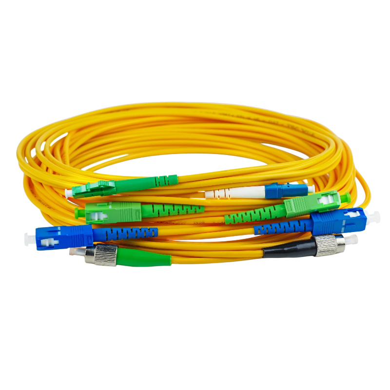
APC (Angled Physical Contact) | 8° angled | Green | FTTH, CATV, PON — superior return loss |
Important: never mate UPC with APC. The mismatched end faces will not make proper contact, causing high insertion loss and potentially permanent damage to the ferrule end faces. Always pair UPC adapters with UPC connectors and APC adapters with APC connectors.
With Flange vs Without Flange
The mounting style determines how the adapter fixes into a panel.
With flange — includes mounting ears / screw holes for secure fixing to patch panels, wall plates, ODFs, and enclosures. Choose when mechanical stability matters.
Without flange — a compact, snap-in body for high-density panels and modular systems where screw mounting is not required.
Key Specifications to Check
The product name alone is not enough — confirm the parameters below before ordering.
Parameter | Typical Value | Why It Matters |
|---|---|---|
Insertion Loss (IL) | ≤0.2dB (typ.) | Power lost across the mated pair; lower is better |
Return Loss (RL) | UPC ≥50dB / APC ≥60dB | How much light is reflected back; higher is better |
Sleeve Material | Zirconia ceramic / phosphor bronze | Ceramic for SM; defines alignment accuracy |
Fiber Mode | OS2 / OM1–OM5 | Must match the installed fiber |
Polish | UPC / APC | Must match the connector polish |
Structure | Simplex / Duplex / Quad | Number of fibers per adapter |
Mounting | With / without flange, SC footprint | Must match the panel cutout and fixing |
Durability | ≥500 mating cycles | Long-term reliability under repeated patching |
Key Features of a Quality LC Adapter
Compact LC form factor for high-density cabling
Precision alignment sleeve for accurate core-to-core alignment
Low insertion loss and stable, repeatable transmission
Single-mode and multimode options
UPC and APC interfaces
Simplex, duplex, and quad configurations
With-flange, without-flange, and SC-footprint mounting
Common Applications
Data centers and high-density structured cabling
Telecom networks, FTTH and FTTx systems
Fiber patch panels and optical distribution frames (ODFs)
Wall plates, faceplates, and equipment cabinets
LAN / enterprise networks and fiber optic test systems
How to Choose the Right LC Adapter
Run through these five checks and you will land on the correct part every time:
Fiber mode — OS2 single mode, or OM1–OM5 multimode.
Polish — match UPC to UPC, APC to APC. Never mix.
Structure — simplex (1 fiber), duplex (2), or quad (4).
Mounting — with flange for screw-mounted panels, without flange for snap-in high density.
Footprint — choose an SC-footprint LC adapter when the cutout is SC-sized but the interface must be LC.
Frequently Asked Questions
Q1: What is the difference between an LC adapter and an LC connector?
The connector terminates the fiber and is attached to the cable end; the adapter is the passive coupler that joins two connectors together and aligns their ferrules. You always need both.
Q2: Can I connect an LC/UPC connector to an LC/APC adapter?
No. UPC and APC end faces have different geometries (flat vs 8° angled). Mating them prevents proper physical contact, causes high insertion loss, and can damage the ferrules. Always keep UPC with UPC and APC with APC.
Q3: Are LC adapters single mode or multimode?
Both are available. Single-mode adapters (OS2) use ceramic sleeves for tighter alignment; multimode adapters serve OM1–OM5 fiber. Choose the adapter that matches your installed fiber.
Q4: What is an LC adapter with SC footprint used for?
It lets you fit LC connectivity into an existing SC-sized panel cutout — the easiest way to upgrade legacy SC panels to higher-density LC without changing the panel.
Q5: What insertion loss should I expect from an LC adapter?
A good-quality LC adapter contributes around ≤0.2dB typical insertion loss across the mated pair. Return loss is usually ≥50dB for UPC and ≥60dB for APC.
Conclusion
LC fiber adapters are essential, deceptively simple components: their precision alignment sleeve is what keeps insertion loss low and transmission stable across single-mode and multimode networks. By confirming fiber mode, connector polish, structure, mounting style, and footprint, you can specify the right LC adapter for any data center, FTTH, telecom, or patch-panel installation.
Firsol supplies LC fiber adapters in simplex, duplex, and quad configurations, in single mode (OS2) and multimode (OM1–OM5), with UPC or APC polish, flange / flangeless / SC-footprint mounting, and custom packaging to match your project.