What Is an MPO Adapter? Types, Polarity & Selection Guide
Inside a high-density fiber link, an MPO adapter looks like nothing more than a small plastic coupler — yet it quietly does one of the most important jobs in the whole channel: it holds two multi-fiber connectors face to face so that every core lines up with its partner at the same moment. In a data center where a single 1U panel can carry hundreds of fibers, the wrong adapter — or the wrong polarity — is the difference between a clean link and hours spent chasing a connection that looks perfect but simply will not pass light.
This guide walks through what an MPO adapter really is, how it works mechanically, the types you will meet on a datasheet (polarity, fiber count, gender and housing), and a practical framework for choosing the right one. The technical points here follow the MPO interface standard IEC 61754-7 and the TIA-568.3 polarity methods, so you can verify a part rather than take it on faith.
What Is an MPO Adapter?
An MPO adapter (often written MPO/MTP adapter) is a fiber optic coupling device built for multi-fiber MPO connectors. It receives one connector from each side and holds them in the correct orientation so that a whole row of fibers — 8, 12, 16 or 24 of them — mates through a single compact interface.
Unlike an LC adapter, which couples just two fibers, an MPO adapter manages an entire array (sometimes two stacked rows). That density is exactly what makes it the backbone of high-density patching, where rack space, airflow and cable routing are all under pressure. You will typically find MPO adapters in:
Data center patch panels and MPO cassettes
Backbone and trunk cabling
Optical distribution frames (ODF)
Migration projects moving 40G / 100G / 400G links to parallel optics
MPO Adapter vs MPO Connector
The two terms travel together but are not the same part. Put simply: the connector is on the cable; the adapter is in the panel.
Item | MPO Adapter | MPO Connector |
|---|---|---|
Main function | Couples and aligns two MPO connectors | Terminates a row of optical fibers |
Where it sits | Mounted in a panel, cassette or adapter plate | Attached to the end of a trunk or patch cable |
Key job | Holds both connectors in the right orientation | Carries the fibers and mates with the opposite connector |
What to check | Polarity, key orientation, housing style, fiber count | Fiber count, gender, ferrule grade, polish, insertion loss |
How Does an MPO Adapter Work?
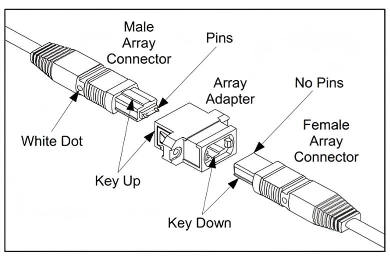
An MPO adapter is a mechanical guide, not an optical component — it usually contains no fiber of its own. When you push a connector in from each side, the adapter housing fixes their orientation and holds the correct mating position so the two ferrules meet squarely.
Housing, key and guide pins
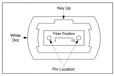
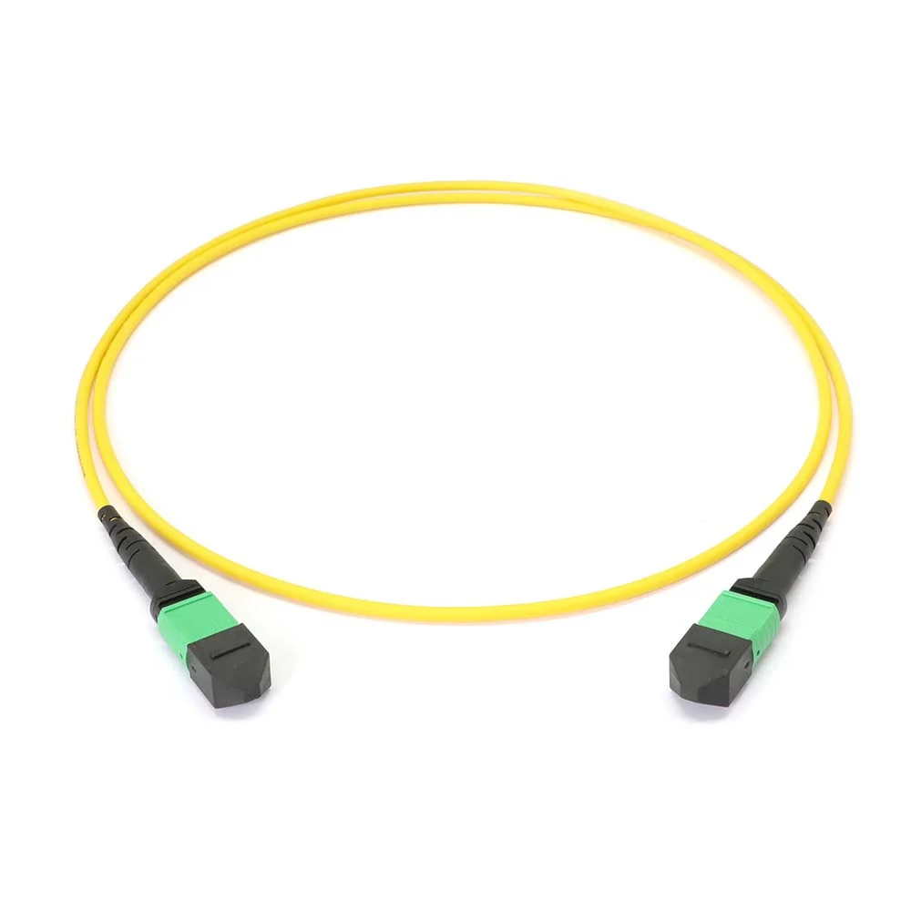
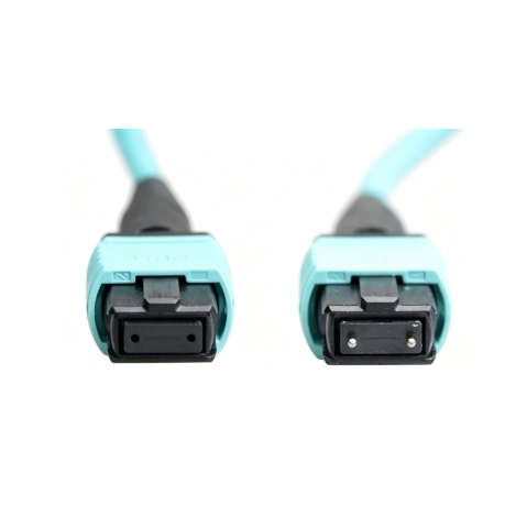
Each MPO connector uses a rectangular multi-fiber (MT) ferrule with a small key on one side of the body. The adapter opening is shaped to that key, so a connector only seats one way. Fine alignment, however, comes from the ferrules themselves: in a correct pair, one connector is pinned (male, with two guide pins) and the other is unpinned (female, with two guide holes). The pins slide into the holes and register the ferrules to within microns. These pin and guide-hole dimensions are defined in IEC 61754-7, which is why compliant parts from different makers can intermate.
Gender is not optional
Because alignment depends on pins seating into holes, every mated point needs exactly one male and one female connector. Two males will not seat (no holes for the pins, and forcing them damages the end faces); two females have nothing to align them. So before you order, trace the gender along the whole link — if your trunk lands female, the cassette or patch cord on the other side has to bring the pins. The adapter cannot fix a gender mismatch; it only holds whatever you give it.
MPO Polarity and Key Orientation
Polarity produces more field errors than anything else in MPO work, because the parts can fit mechanically while the optical path is wrong. In a duplex link, one fiber transmits and one receives — and across a multi-fiber MPO that transmit/receive relationship has to survive every trunk, cassette and patch cord in the channel. Polarity is a property of the whole link, not of any single adapter.
Type A, Type B and Type C
TIA-568.3 describes three array polarity types, differing in how fibers are mapped end to end and how the connectors are keyed:
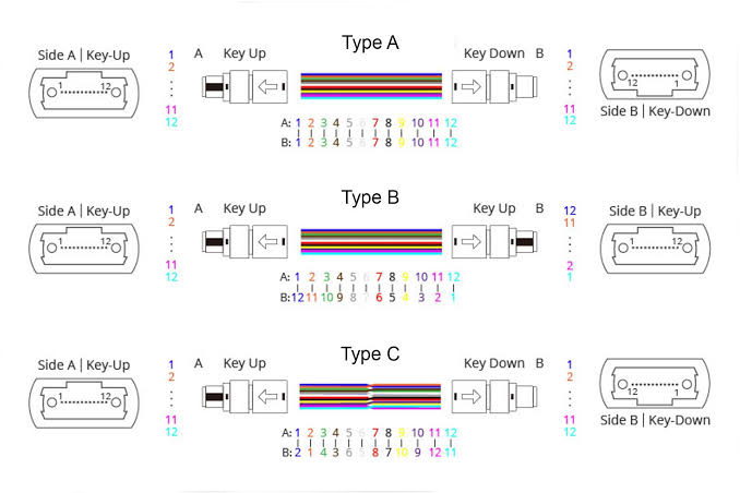
Type | Fiber mapping | Key orientation | Where it fits |
|---|---|---|---|
Type A (straight) | Position 1 → position 1 | Key-up to key-down | Cassette-based structured cabling; channel needs one flipped patch cord |
Type B (reversed) | Position 1 → position 12 | Key-up to key-up | Common for direct parallel optics; same patch cords at both ends |
Type C (pair-flipped) | Position 1 → position 2, in swapped pairs | Key-up to key-down | Some duplex MPO-to-LC systems |
All three are valid and standards-compliant, and all three get transmit on one end to receive on the other. The catch: they are not interoperable if you mix them. Pick one method for the entire installation and keep it consistent.
Reading key-up and key-down
Key-up means the connector's key tab points up; key-down means it points down. With the key up and the end face toward you, position 1 sits on the far left. Whether two mated connectors meet key-up/key-down or key-up/key-up is exactly what decides a straight vs reversed mapping — so on a datasheet the key relationship is a direct clue to polarity. One trap: reversing positions also reverses the angled end face on APC singlemode connectors, so Type B is usually a multimode, flat-polish convention. If you are working with APC, confirm the polish and angle before assuming a method.
MPO vs MTP: Are They the Same?
You will often see parts labeled "MPO/MTP" and wonder whether they are two different things. MTP® is a registered trademark of US Conec for its own enhanced MPO connector, built to tighter tolerances with a floating ferrule and a metal pin clamp. By definition an MTP connector is fully MPO-compliant, so MTP and generic MPO intermate. Put plainly: every MTP is an MPO, but not every MPO is an MTP.
For an adapter, a quality MPO coupler will mate MTP and generic MPO connectors alike — the practical differences in loss consistency and mating-cycle durability live mostly in the connector, not the coupler. When a spec says "MTP", it is worth checking whether the customer means the US Conec brand specifically or is using the word loosely for any MPO, because that single distinction changes price and sourcing.
Types of MPO Adapters
By fiber count: 8, 12, 16 and 24
8 and 12 fiber: 40G-SR4 and 100G-SR4 use 8 fibers, often housed inside a 12-fiber MPO; singlemode 400G-DR4 also uses 8 fibers in an MPO-12.
16 fiber: 400G-SR8 and the 800G variants use 16 fibers (8 transmit, 8 receive) in an MPO-16.
24 fiber: a two-row format for very high density and some legacy 100G-SR10 links.
An MPO-12 and an MPO-16 are not interchangeable — they differ in ferrule width and key, so the adapter opening differs too. Confirm the count on both the connector and the panel before you buy.
Singlemode vs multimode
Aspect | Singlemode (OS2) | Multimode (OM3/OM4/OM5) |
|---|---|---|
Typical reach | Longer reach, tight loss budgets | Short-reach, high-speed inside the data center |
Common polish | Often APC (angled) | Usually UPC (flat) |
Housing color clue | Blue / green | Aqua (OM3/OM4), violet (OM4), lime (OM5) |
The fiber type drives the connector polish, performance grade and often the housing color.
Color code and housing
Color is a useful first clue — aqua usually signals OM3/OM4, magenta or erika violet often OM4, lime green OM5, and blue or green is common for singlemode. But it is a clue, not a guarantee: manufacturers vary, and the UPC-vs-APC choice also affects body color. Always read the datasheet for fiber type, polarity and grade rather than buying on housing color alone.
Flanged vs flangeless
This is a panel-fit decision more than a performance one.
Aspect | Flanged | Flangeless |
|---|---|---|
Mounting | Screw-fixed to a metal panel | Snap-in clip, tool-less |
Best when | Fixed ODF/patch panels, frequent re-patching | High-density modular panels and cassettes |
Trade-off | Stronger hold, slower to mount | Quick to mount, retention relies on the panel cutout |
Typical MPO Adapter Specifications
Exact figures depend on grade and fiber type, but a quality MPO adapter (with matched low-loss connectors) will generally fall within these ranges:
Parameter | Typical value |
|---|---|
Fiber count | 8F / 12F / 16F / 24F |
Fiber type | Singlemode OS2 / Multimode OM3, OM4, OM5 |
Insertion loss (per mated pair, low-loss grade) | ≤ 0.35 dB typical, ≤ 0.5 dB max |
Return loss (UPC / APC) | ≥ 30 dB (UPC MM) / ≥ 60 dB (APC SM) |
Polarity types | Type A / B / C |
Housing style | Flanged / flangeless |
Durability | ≥ 500 mating cycles |
Operating temperature | -40°C to +75°C |
Compliance | IEC 61754-7, TIA-568.3, RoHS |
Where Are MPO Adapters Used?
Data centers. In patch panels, on cassette rears and at trunk-to-trunk joins. A high-count trunk lands on a panel, then breaks out through cassettes to LC duplex ports. Selection note: match the cassette's polarity type and key orientation, or the breakout will not preserve transmit and receive.
Telecom & ODF. MPO consolidates many fibers into compact optical distribution frames and central-office routing.
Cassettes & breakout. Many cassettes use MPO at the rear and LC at the front, turning one trunk into duplex patching ports.
High-speed migration. Moving from duplex to parallel optics — 400G-SR8, for example, runs 16 fibers over an MPO-16 per IEEE 802.3.
How to Choose an MPO Adapter: A 6-Step Framework
Rather than picking by shape, work down the channel in order:
Confirm the link type. Direct MPO-to-MPO, or an MPO trunk feeding cassettes that break out to LC?
Confirm the transceiver interface. Note fiber count and connector — e.g. 100G-SR4 at 8 fibers, or 400G-SR8 at 16 fibers (often APC).
Confirm the trunk fiber count. MPO-8, 12, 16 or 24; the adapter must match.
Confirm cassette vs direct. Cassettes set the polarity mapping for you; a direct link pushes polarity onto the trunk and patch cords.
Confirm key orientation and housing. Key-up/key-down or key-up/key-up for your method, and flanged or flangeless for your panel.
Confirm loss budget and cleanliness. Choose the insertion-loss grade your budget needs, and plan to inspect and clean before mating.
Worked Example: A Data Center Patch Panel
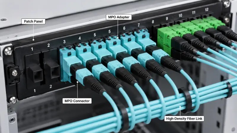
Say you are landing a 24-fiber OM4 MPO trunk on a 1U panel and breaking it out to LC duplex for 100G-SR4 switches. The trunk connectors are female and the cassette MPO connectors are male, so a standard adapter mates them with no gender clash. You have standardized on Method B, so cassettes and trunk are Type B and connectors meet key-up to key-up; the adapter simply has to support that orientation and the cassette's fiber-count format. You choose flangeless adapters (dense snap-in panel), aqua housing (OM4) and a low-loss grade (the channel already spends budget on two cassette mates). Before patching, you inspect each ferrule — skip the polarity check and the whole panel quietly transmits into transmit.
Inspect and Clean Before You Mate
An MPO ferrule packs many end faces into one surface, so a single speck can take down more than one channel. On 16- and 24-fiber ferrules the height variation across fibers makes uniform cleaning harder — which is why the rule is inspect, clean, then inspect again. Contamination shows up as higher insertion loss, higher reflectance and intermittent links that are slow to trace in a dense panel. Use proper MPO inspection and cleaning tools before every mate.
Common Mistakes — and What They Cost
Ignoring polarity. The parts fit, but transmit lands on transmit. The link is dark and you lose time tracing a connection that looks correct.
Treating MPO and MTP as identical in quality. Both mate, but loss and durability differ; assuming parity can quietly blow a tight budget.
Buying on color alone. Aqua does not confirm grade, polarity or polish — the datasheet does.
Forgetting gender. Two pinned or two unpinned connectors will not align, and forcing them scratches the end faces.
No upgrade plan. Parts chosen only for today may not re-home cleanly to 400G or 800G later.
RFQ Specification Checklist
When you send a quote request, give the supplier these details so the right part ships the first time:
Fiber count: 8F, 12F, 16F or 24F
Fiber type: singlemode (OS2) or multimode (OM3/OM4/OM5)
Polarity type: A, B or C
Key orientation: key-up/key-down or key-up/key-up
Connector gender used in the link
Housing: flanged or flangeless, plus color and material
Operating temperature range
Insertion-loss grade or link-budget target
Dust caps, and adapter plate / panel cutout compatibility
Compliance (RoHS) plus a test report
Frequently Asked Questions
Does an MPO adapter contain fiber?
No. It is a purely mechanical coupler. Alignment comes from the connector ferrules and their guide pins/holes — the adapter only holds the two connectors in the correct orientation.
Can I mate an MPO connector with an MTP connector?
Yes. MTP is a fully MPO-compliant connector, so MTP and generic MPO intermate through the same adapter. Differences in loss and durability come from the connector, not the adapter.
Why won't my two MPO connectors seat together?
Most likely a gender mismatch. A working mated pair needs exactly one pinned (male) and one unpinned (female) connector. Two of the same gender will not align — never force them, as it can damage the end faces.
Are MPO-12 and MPO-16 adapters interchangeable?
No. They use different ferrule widths and keys, so the adapter opening differs. Match the adapter to the exact connector format you are deploying.
How do I know which polarity type I need?
Follow the channel. Cassette-based structured cabling typically uses Type A; direct parallel-optics links commonly use Type B. Whatever you choose, keep one method consistent across the entire installation — mixing types breaks the link.
Conclusion
An MPO adapter is a small part with an outsized influence on a high-density link. Get the fiber count, gender, polarity and housing right — and inspect before every mate — and it disappears into a clean, reliable channel. Get any of them wrong, and you inherit a panel that fits perfectly yet passes no light.
Need MPO/MTP adapters for your next build? Firsol supplies MPO-8/12/16/24 adapters in singlemode and multimode, flanged and flangeless, in all three polarity types with test reports. Contact our technical team for a datasheet or a quote tailored to your channel.