FWDM Explained: Filter WDM Types, Specs & How to Choose
Filter WDM — commonly written as FWDM, Filter-based WDM, or Thin Film Filter WDM — is one of the most widely deployed wavelength multiplexing technologies in modern fiber optic networks. From FTTH triplexers and EDFA pump combiners to CATV overlay and instrumentation, FWDM quietly sits inside almost every optical link that needs to merge or separate two or three wavelengths with low loss and high isolation.
This guide breaks down what FWDM is, the common wavelength variants, typical performance specs, and how to choose the right configuration for your application.
What is FWDM?
FWDM is a passive wavelength division multiplexer built around a Thin Film Filter (TFF). The filter itself is a glass substrate coated with dozens of alternating high- and low-refractive-index dielectric layers. Because of wavelength-dependent interference at every layer interface, the filter transmits one wavelength band and reflects another.
In a typical 1310/1550 nm FWDM, light entering the common port is split: 1310 nm passes straight through the filter, while 1550 nm reflects off the coating and exits through a separate fiber pigtail — or vice versa, depending on the design. Because the device is fully passive and bidirectional, the same FWDM can act as a multiplexer (combiner) or demultiplexer (splitter).
Compared to AWG or fused-fiber WDMs, FWDM offers very low insertion loss, low polarization dependence, high channel isolation, a flat-top passband, and excellent thermal stability. High-power variants — built with epoxy-free optical paths and high-quality AR coatings — can handle several watts of optical power, which is why FWDM dominates EDFA, fiber laser and high-power CATV designs.
FWDM vs CWDM vs DWDM vs AWG — Quick Comparison
Before choosing FWDM, it helps to understand where it fits in the broader WDM landscape.
Technology | Channels | Channel Spacing | Typical IL | Best For |
|---|---|---|---|---|
FWDM (TFF) | 2 – 4 | Wide (e.g. 1310/1550 nm) | 0.3 – 0.6 dB | FTTx, EDFA, CATV, instrumentation |
CWDM | Up to 18 | 20 nm | 0.8 – 1.5 dB | Metro / access aggregation |
DWDM | 40 / 80 / 96+ | 100 / 50 GHz | 3.0 – 6.0 dB | Long-haul, high-capacity backbone |
AWG | 40 / 96+ | 100 / 50 GHz | 3.5 – 5.0 dB | High-channel-count DWDM nodes |
Rule of thumb: if you only need to combine or separate 2 – 4 widely-spaced wavelengths, FWDM is almost always the lowest-loss and lowest-cost choice.
Common FWDM Wavelength Types
FWDMs are typically named by the wavelengths they combine. The table below covers the eight configurations most commonly deployed in carrier and enterprise networks.
Type | Typical Application |
|---|---|
850 / 1310 nm | Multimode fiber links, CATV, test instruments |
1310 / 1550 nm | General WDM / CATV overlay on single-mode fiber |
980 / 1550 nm | High-performance EDFA pump / signal combiners |
1480 / 1550 nm | High-power EDFA pump combining |
1510 / 1550 nm | DWDM multi-channel optical networks, OSC |
1310 / 1490 / 1550 nm | PON / FTTH triplexers, test gear |
1310 / 1550 / 1625 nm | In-service fiber monitoring (OTDR overlay at 1625 nm) |
1310 / 1490 / 1550 / 1625 nm | Adding 1625 nm monitoring to existing triplex FTTH systems |
For DWDM systems, two TFF-based cousins are also widely used:
C-Band / L-Band FWDM — separates or combines C-band and L-band traffic in DWDM amplifier nodes.
C-Band Red / Blue FWDM — splits the C-band into Red and Blue halves so each half can be amplified or filtered independently.
C-Band / L-Band Supervisory FWDM — adds or drops the optical supervisory channel (OSC) inside EDFA shelves.
Typical FWDM Performance Specs
When evaluating FWDM components, the four parameters that matter most are insertion loss, channel isolation, polarization-dependent loss and optical power handling. Below are representative values for Firsol’s FWDM product line.
Parameter | Standard Grade | High-Power Grade |
|---|---|---|
Insertion Loss (IL) | ≤ 0.5 dB | ≤ 0.7 dB |
Channel Isolation | ≥ 25 dB (adjacent) / ≥ 40 dB (non-adjacent) | ≥ 25 dB |
Polarization Dependent Loss (PDL) | ≤ 0.1 dB | ≤ 0.15 dB |
Return Loss | ≥ 50 dB | ≥ 50 dB |
Optical Power Handling | 300 mW | ≥ 5 W |
Operating Temperature | −5 to +70°C | −5 to +70°C |
Package | Ø5.5 × 35 mm mini tube | Ø5.5 × 35 mm mini tube |
How to Choose the Right FWDM
Use this short checklist when specifying an FWDM for a new design:
Pick the wavelength set first. Match it to your transceivers, EDFA pump scheme or OTDR monitoring plan. Don’t over-spec — a 1310/1550 nm device costs a fraction of a 1310/1490/1550/1625 nm quad.
Decide on fiber type. Single-mode (G.652D) covers almost all telecom and FTTx use. Choose multimode FWDM only for legacy 850 nm links.
Check power handling. For EDFA pump combining, fiber laser front-ends or high-power CATV, specify the high-power grade (≥ 1 W, ≥ 5 W).
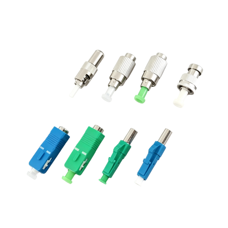
Confirm connector type and polish. SC/APC and LC/APC are standard for PON and CATV; FC/UPC and bare-fiber pigtails are common in lab and EDFA work.
Mind isolation, not just IL. For overlay systems carrying analog CATV or coherent signals, ≥ 40 dB non-adjacent isolation is the spec that prevents crosstalk-driven noise.
Where FWDM Is Used
FTTH / PON — triplexer and quad modules for 1310 / 1490 / 1550 / 1625 nm
EDFA & Raman amplifiers — pump/signal combining at 980 nm and 1480 nm
CATV overlay — adding 1550 nm video onto existing 1310 nm data links
In-service fiber monitoring — injecting 1625 nm OTDR traces without disturbing traffic
Fiber lasers & instruments — high-power signal combining and beam routing
Metro & access networks — supervisory channel add/drop in DWDM nodes
FAQ
What is the difference between FWDM and CWDM?
FWDM typically combines 2 – 4 wavelengths with very wide spacing (e.g. 1310/1550 nm) using a single thin-film filter, giving sub-0.6 dB insertion loss. CWDM uses a cascade of TFF filters at 20 nm spacing to multiplex up to 18 channels, but each added channel adds insertion loss. Use FWDM when you only need a handful of widely separated wavelengths.
Can FWDM handle high optical power?
Yes. High-power FWDMs use epoxy-free optical paths and premium AR coatings to handle 1 W to 5 W of continuous power, which is why they are the default choice for EDFA pump combiners and fiber laser front-ends.
Is FWDM bidirectional?
Yes. Because the device is fully passive, the same FWDM works as a multiplexer or a demultiplexer depending on which port you feed light into.
What does “isolation” mean on an FWDM datasheet?
Isolation is how strongly the device rejects the unwanted wavelength on each output port, measured in dB. Adjacent-channel isolation of ≥ 25 dB is standard; non-adjacent isolation of ≥ 40 dB is required for high-fidelity overlay applications.
Firsol FWDM Solutions
Firsol supplies the full range of FWDM modules — from standard 1310/1550 nm splitters and FTTH triplexers to high-power EDFA pump combiners and C-band / L-band DWDM filters. All modules are tested for IL, PDL, isolation and return loss, and ship with full datasheets.
Need a specific wavelength combination, connector type or power rating? Contact our engineering team for a free quote — we typically respond within one business day.