What Is an Arrayed Waveguide Grating (AWG) and How Does It Work?
Modern optical networks must transport an enormous and continually growing volume of data. Wavelength division multiplexing (WDM) increases fiber capacity by allowing several optical channels, each carried at a different wavelength, to travel through the same fiber. At the two ends of the link, those wavelengths must be combined and separated accurately. An arrayed waveguide grating, commonly abbreviated as AWG, is one of the most effective integrated-optics devices for performing this task.
AWGs are widely used as optical multiplexers and demultiplexers in dense wavelength division multiplexing (DWDM) systems. They can support many channels in a compact package while providing predictable channel spacing, low insertion loss, and high isolation. AWGs are also used in wavelength-routed access networks, optical add/drop architectures, photonic signal processing, and spectroscopy.
This guide explains what an AWG is, how it separates wavelengths, the main AWG types, why temperature control matters, and which specifications should be considered when selecting a device.
What Is an Arrayed Waveguide Grating?
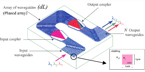
An arrayed waveguide grating is a planar lightwave circuit that routes optical signals according to wavelength. In a demultiplexer configuration, a multiwavelength signal enters a common input port and the AWG directs each wavelength to a designated output channel. When operated in the reverse direction, signals from multiple wavelength-specific input ports are combined into one common output, so the same basic structure can function as a multiplexer.
The word “arrayed” refers to the large set of parallel waveguides inside the chip. Adjacent waveguides are designed with a constant difference in optical path length. As light travels through the array, this path-length difference creates a wavelength-dependent phase shift. The fields emerging from the waveguides then interfere in a controlled way, causing different wavelengths to focus at different positions.
An AWG performs a function similar to a diffraction grating in free space, but the optical paths are formed inside an integrated waveguide chip. This planar construction makes the device compact, stable, repeatable, and suitable for multi-channel production.
Main Components of an AWG
Although package styles and material platforms vary, a conventional AWG contains five functional sections:
Input waveguide: carries the composite optical signal into the chip.
Input free propagation region (FPR): allows the incoming field to expand and illuminate the arrayed waveguides. It is also called a slab waveguide or star coupler.
Arrayed waveguides: a group of waveguides whose lengths increase by a fixed amount from one waveguide to the next.
Output free propagation region: recombines the fields leaving the array and focuses different wavelengths at different lateral positions.
Output waveguides: collect the separated wavelength channels and connect them to the output fibers.
The two free propagation regions are essential. The first distributes light across the array, while the second converts the phase relationship created by the array into spatial wavelength separation.
How Does an AWG Work?
1. The input signal spreads across the array
A WDM signal containing wavelengths λ1, λ2, λ3, and so on enters the input waveguide. When it reaches the first free propagation region, diffraction causes the optical field to spread across many arrayed waveguides. Each waveguide therefore receives a portion of every wavelength in the input signal.
2. Each waveguide introduces a controlled phase delay
The physical length of each arrayed waveguide is slightly longer than that of its neighbor. The phase accumulated by light depends on wavelength, refractive index, and propagation length. A simplified expression is φ = 2πn_effL/λ, where n_eff is the effective refractive index, L is the propagation length, and λ is the vacuum wavelength.
Because adjacent waveguides have a fixed length difference ΔL, they introduce a fixed incremental phase delay for a selected center wavelength. Changing the wavelength changes that phase relationship. This wavelength-dependent phase slope across the array is the basis of AWG wavelength routing.
3. The fields interfere in the output region
At the second free propagation region, the optical fields from all arrayed waveguides overlap. For a particular wavelength, the fields add constructively at a particular position. A slightly different wavelength produces a different phase slope and therefore focuses at a different position. Output waveguides placed at these focal positions collect the individual channels.
The important point is not that different wavelengths simply interfere with one another. Instead, each wavelength experiences its own phase relationship across the array, and that relationship determines where the wavelength is focused.
AWG Multiplexer and Demultiplexer Operation
AWGs are reciprocal passive devices. In demultiplexer operation, the common port receives a multiwavelength signal and the channel ports provide separated outputs. In multiplexer operation, individual wavelength channels enter the channel ports and combine at the common port. Some modules contain separate AWG chips or optical paths for MUX and DeMUX functions, while others use one reciprocal optical circuit according to the system design.
A complete DWDM module may also include connectors, fiber pigtails, monitor taps, variable optical attenuators, photodiodes, or other components. These additions support power monitoring, channel equalization, protection, or system management, but the AWG remains the wavelength-selective element.
Main Types of AWG
AWGs can be classified by passband shape, thermal-control method, material platform, channel plan, and spectral behavior. These classifications describe different aspects of the same device and often overlap.
Gaussian and Flat-Top AWGs
Passband type | Main characteristics | Typical consideration |
Gaussian | Rounded spectral response with the lowest loss near the channel center. | Efficient when source wavelength and system alignment are tightly controlled. |
Flat-top | Broader, flatter usable region around the center wavelength. | Provides more tolerance to laser drift and filter cascading, usually with some insertion-loss tradeoff. |
Semi-flat | Compromise between Gaussian loss performance and flat-top bandwidth. | Useful when both loss and passband tolerance are important. |
Passband shape should be selected according to the transmitter stability, channel bandwidth, data rate, number of cascaded filters, and the acceptable insertion-loss budget. A flat-top response is not automatically superior; it offers a wider usable passband but may involve higher loss or more complex design.
Thermal and Athermal AWGs
The refractive index and physical dimensions of an AWG change with temperature. These changes shift the wavelength response, so temperature behavior must be addressed when the device is expected to remain aligned with a fixed channel grid.
A thermal AWG uses a heater, temperature sensor, and control circuit to stabilize the chip at a predefined operating temperature. Active control can provide precise wavelength alignment over a wide environmental range, but it consumes electrical power and requires control electronics.
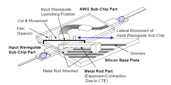
An athermal AWG uses passive compensation to reduce wavelength drift. Depending on the design, compensation may use materials with different thermal expansion or thermo-optic properties, a mechanically responsive package, or a combination of both. Athermal AWGs require no active heater, making them attractive for passive modules, outdoor equipment, access networks, and installations where low power consumption is important.
Feature | Thermal AWG | Athermal AWG |
Wavelength stabilization | Active heater and feedback control | Passive material or package compensation |
Electrical power | Required | Not required for wavelength stabilization |
System complexity | Includes sensor and control electronics | Simpler passive deployment |
Typical advantage | Precise controlled operating point | Low power and compact passive operation |
Selection factor | Available power, control needs, temperature range | Residual wavelength drift and specified operating range |
Material Platforms and Index Contrast
Silica-on-silicon PLC technology is widely associated with telecom AWGs because silica waveguides can offer low propagation loss and good mode compatibility with optical fiber. Lower refractive-index contrast generally supports easier fiber coupling and low polarization sensitivity, but it requires larger bend radii and therefore a larger chip area.
Higher-index-contrast platforms can create tighter bends and smaller devices. Examples include silicon, silicon nitride, indium phosphide, and other integrated photonic materials. Their compactness supports dense integration, but coupling loss, polarization behavior, fabrication tolerance, dispersion, and thermal sensitivity must be carefully managed. The best platform depends on wavelength range, channel spacing, footprint, integration requirements, and target cost.
Cyclic and Colorless AWGs
A conventional AWG has a periodic spectral response described by its free spectral range. A cyclic AWG intentionally uses this periodicity so that the same output-port pattern repeats across multiple wavelength bands. The device may route channels by wavelength “color” without permanently assigning it to only one narrow group of absolute wavelengths. Cyclic AWGs are useful in colorless routing, interleaving, wavelength-selective access, and some reconfigurable optical-network architectures.
Channel Count and Channel Spacing
AWGs are available with many channel configurations, including 8, 16, 32, 40, 48, 64, 80, 96, and custom port counts. Channel count should not be confused with the number of waveguides inside the phased array; the internal array usually contains many more waveguides than the number of external wavelength channels.
Common DWDM spacings include 200 GHz, 100 GHz, 50 GHz, and 25 GHz. Near 1550 nm, 100 GHz corresponds to approximately 0.8 nm and 50 GHz to approximately 0.4 nm, but these wavelength differences are only approximations. The DWDM grid is defined in frequency, so the wavelength difference corresponding to a fixed frequency interval varies across the spectrum.
Narrower spacing increases spectral efficiency but places tighter requirements on wavelength accuracy, passband width, temperature stability, crosstalk, and transmitter control. The correct spacing must therefore be selected as part of the complete optical-system design.
Key AWG Performance Parameters
A channel count alone does not describe AWG performance. When comparing devices, review the following specifications together:
Operating wavelength and channel grid: define the supported spectral band, reference frequency, channel numbering, and spacing.
Insertion loss: optical power lost between the relevant input and output ports. Both typical and maximum values should be considered in the link budget.
Loss uniformity: the difference between the highest- and lowest-loss channels. Good uniformity simplifies channel power management.
Channel passband: the spectral range over which a channel meets the specified loss or ripple limit.
Adjacent-channel isolation: rejection of power from the immediately neighboring channels.
Non-adjacent isolation: rejection of channels farther away from the selected passband.
Crosstalk: unwanted optical power appearing at an incorrect output, often influenced by fabrication errors, phase noise, and packaging alignment.
Polarization-dependent loss (PDL): change in insertion loss with input polarization state.
Polarization-mode dispersion (PMD): differential delay between polarization modes, important in high-speed transmission.
Passband ripple: variation in insertion loss across the usable channel bandwidth.
Wavelength accuracy and thermal drift: indicate how closely the channel centers follow the specified grid across temperature.
Return loss and directivity: describe reflections and unwanted coupling paths within the packaged component.
Specifications should be compared using consistent definitions and test conditions. For example, a low typical insertion loss does not guarantee adequate performance if maximum loss, uniformity, isolation, or temperature drift is unsuitable for the intended link.
AWG Applications
DWDM Multiplexing and Demultiplexing
The most established AWG application is combining and separating many closely spaced wavelength channels in metro, long-haul, data-center interconnect, and transport networks. High channel counts allow a single fiber pair to carry far more aggregate capacity without installing additional transmission fiber.
Optical Add/Drop and Cross-Connect Systems
In optical add/drop multiplexers, AWGs separate wavelength channels so selected channels can be added, dropped, monitored, attenuated, or switched while the remaining traffic continues through the node. In optical cross-connect and wavelength-routing systems, AWGs can work with optical switches, wavelength-selective elements, and variable optical attenuators to direct channels between network paths.
WDM-PON and Access Networks
In wavelength division multiplexed passive optical networks, an AWG can route different wavelengths to different subscribers or optical network units. Its wavelength-routing property enables logical point-to-point connections over a shared passive distribution system. Athermal operation is especially useful where remote equipment must operate without electrical power.
Optical Monitoring and Spectroscopy
Because an AWG maps wavelength to position, it can act as a compact spectrometer or channel monitor. AWGs are used in sensing, biomedical instrumentation, laboratory analysis, laser monitoring, and integrated photonic systems. Designs outside the conventional telecom bands may operate at visible, near-infrared, or mid-infrared wavelengths, depending on the waveguide material and detector platform.
Photonic Integration and Signal Processing
AWGs can be integrated with lasers, modulators, photodetectors, optical switches, semiconductor optical amplifiers, and monitoring circuits. This integration supports compact transceivers, wavelength-selective transmitters and receivers, programmable photonic circuits, and other applications that require many optical channels on one chip or in one module.
AWG vs. Thin-Film Filter MUX/DeMUX
Both AWGs and thin-film filters can build WDM multiplexers and demultiplexers, but their strengths are different. Thin-film filter modules cascade wavelength-selective filters that transmit one band and reflect others. They are widely used for CWDM and lower channel counts, and they can provide strong isolation and flexible wavelength combinations.
AWGs perform parallel wavelength routing in a planar circuit and are particularly attractive for high channel counts and closely spaced DWDM grids. The preferred technology depends on channel count, spacing, passband requirements, insertion loss, isolation, package size, temperature range, and production volume. Neither technology is universally better; the system requirements should determine the choice.
How to Select an AWG
Start with the network channel plan, then work outward to environmental and packaging requirements. A practical selection process includes:
Confirm the wavelength band, reference grid, channel count, and channel spacing.
Choose Gaussian, semi-flat, or flat-top passbands according to laser stability and usable bandwidth.
Define maximum insertion loss, loss uniformity, adjacent isolation, and non-adjacent isolation.
Check PDL, PMD, return loss, and ripple against the transmission format and data rate.
Select thermal or athermal control based on the operating-temperature range, available power, and wavelength-stability requirement.
Specify fiber type, pigtail length, connector type, package dimensions, and port labeling.
For custom systems, identify any monitor ports, taps, VOA integration, special channel plan, or bidirectional requirement.
When requesting a custom AWG, it is helpful to provide the complete channel table rather than only the nominal center wavelength. This reduces ambiguity about channel numbering, start and stop frequencies, passband limits, and skipped or reserved channels.
Frequently Asked Questions
Is an AWG an active or passive optical device?
The wavelength-routing chip itself is passive. An athermal AWG can operate without electrical power. A thermal AWG module includes active temperature-control electronics, but its optical multiplexing and demultiplexing function remains passive.
Can the same AWG be used as both a MUX and a DeMUX?
In principle, yes. AWGs are reciprocal, so reversing the propagation direction reverses the function. Practical modules may still be packaged, labeled, optimized, or combined differently for the transmit and receive sides of a system.
Why does an AWG wavelength shift with temperature?
Temperature changes both the effective refractive index of the waveguides and the physical dimensions of the optical paths. These changes alter the phase relationship across the array and shift the channel-center wavelengths.
Does a larger channel count mean the AWG has the same number of arrayed waveguides?
No. External channels and internal arrayed waveguides are different quantities. The phased array typically contains many waveguides to create the required focusing resolution and spectral response.
When should a flat-top AWG be selected?
A flat-top AWG is useful when the system needs a wider low-loss passband, greater tolerance to laser wavelength drift, or better performance after multiple filters are cascaded. The benefit should be balanced against the device's specified insertion loss and ripple.
Conclusion
An arrayed waveguide grating is a compact planar device that combines or separates optical channels by creating wavelength-dependent phase differences across an array of unequal-length waveguides. Its parallel wavelength-routing capability makes it especially valuable in high-channel-count DWDM systems, but the same principle also supports access networks, optical add/drop nodes, channel monitoring, sensing, and integrated photonics.
Selecting the right AWG requires more than choosing a port count. Channel spacing, passband shape, insertion loss, isolation, polarization performance, thermal behavior, packaging, and the complete channel plan must all match the application. Thermal AWGs provide actively controlled wavelength stability, while athermal AWGs offer passive operation and low power consumption. Gaussian, semi-flat, and flat-top designs provide different balances between loss and usable bandwidth.
Firsol supplies optical WDM components and supports customized wavelength plans, fiber configurations, connectors, and package options. For an AWG recommendation or custom MUX/DeMUX requirement, provide your channel count, channel spacing, operating band, passband preference, and environmental requirements to the Firsol team.