DFB 14-Pin Butterfly Laser Diodes: Working Principle, Key Specifications, and Selection Guide
DFB 14-pin butterfly laser diodes are compact semiconductor laser modules designed to provide stable, narrow-linewidth, single-frequency optical output. By combining a distributed feedback laser chip with temperature-control and monitoring components in a hermetically sealed package, these devices offer the wavelength stability and reliability required for demanding optical systems.
They are widely used in DWDM transmission, fiber-optic sensing, spectroscopy, test and measurement, and other applications that require precise wavelength control.
This guide explains how a DFB butterfly laser works, what is normally integrated inside the package, which specifications matter most, and how to select the appropriate wavelength, output power, fiber type, and connector.
What Is a DFB Laser Diode?
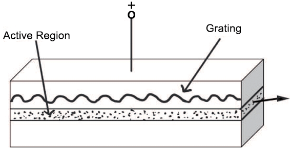
DFB stands for distributed feedback. Unlike a conventional Fabry–Pérot laser, a DFB laser incorporates a periodic grating within or close to the active region of the semiconductor chip.
The grating provides wavelength-selective optical feedback along the laser cavity. It suppresses unwanted longitudinal modes and allows the laser to operate predominantly at one selected wavelength.
As a result, DFB lasers are known for:
Single-longitudinal-mode operation
Narrow spectral linewidth
High side-mode suppression ratio
Stable center wavelength
Low relative intensity noise
Good suitability for wavelength-sensitive systems
The actual performance depends on the laser chip, drive current, operating temperature, optical feedback, and package design.
It is also important to distinguish linewidth from wavelength stability. Linewidth describes the spectral width of the laser output, while wavelength stability describes how much the center wavelength moves as temperature, current, or operating time changes.
Why Use a 14-Pin Butterfly Package?
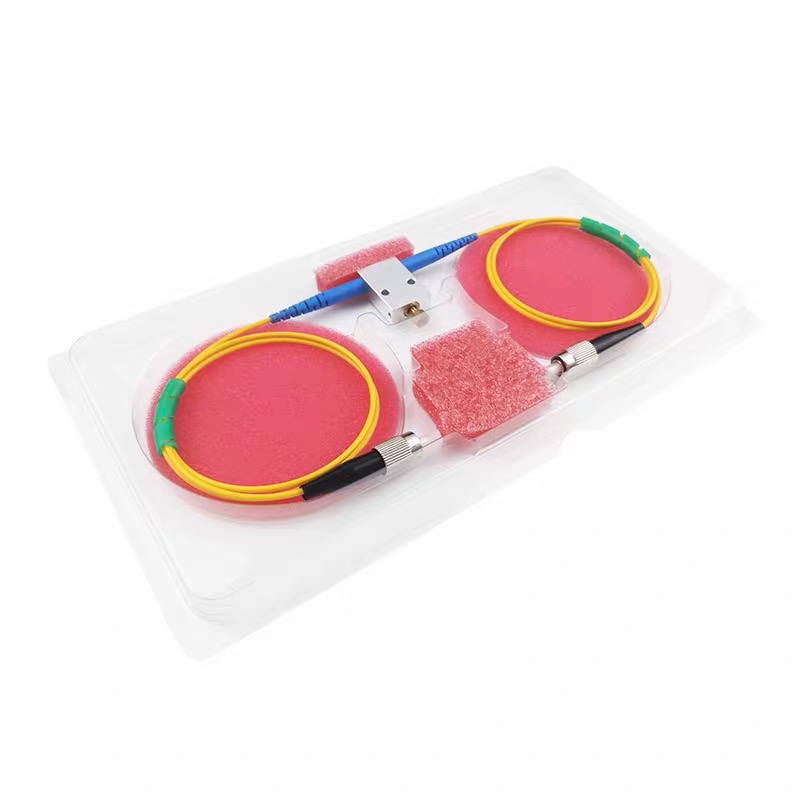
The 14-pin butterfly package is a widely used format for fiber-coupled semiconductor lasers. Its metal housing provides mechanical protection, efficient heat transfer, and a stable platform for optical alignment.
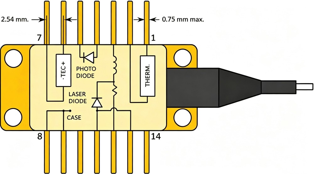
A typical DFB 14-pin butterfly laser diode may integrate the following components:
Component | Function |
|---|---|
DFB laser chip | Generates narrow-linewidth optical output |
Thermoelectric cooler | Regulates the laser temperature |
Thermistor | Measures the internal temperature |
Monitor photodiode | Monitors optical output power |
Optical isolator | Reduces reflected light returning to the laser |
Fiber pigtail | Delivers the optical output to the system |
Hermetic housing | Protects internal optical components from the environment |
The 14 electrical pins provide access to the laser diode, TEC, thermistor, monitor photodiode, and other internal circuits.
Several 14-pin butterfly pinout conventions are used. Type 1 is commonly associated with pump lasers, while Type 2 is commonly used for telecom lasers. The positions of the laser diode, TEC, thermistor, and monitor photodiode pins differ between these configurations. Some Type 2 packages also include a bias-T input for RF modulation. Always follow the pin diagram supplied with the specific laser model.
The Importance of Temperature Control
The output wavelength of a semiconductor laser changes with both temperature and injection current. Even a high-performance DFB chip cannot maintain its specified wavelength if its operating temperature is not properly controlled.
The integrated TEC and thermistor form a closed-loop temperature-control system:
The thermistor measures the laser temperature.
The TEC controller compares the measured temperature with the setpoint.
The controller drives the TEC to heat or cool the laser.
The laser remains near the selected operating temperature.
Stable temperature control helps maintain the center wavelength, output power, SMSR, and overall spectral performance.
A 14-pin butterfly laser therefore normally requires two separate control functions:
A low-noise laser diode current driver
A compatible bidirectional TEC controller
Understanding ITU-Grid DFB Laser Diodes
For DWDM applications, wavelengths are normally specified according to an ITU frequency grid rather than by an approximate wavelength such as “1550 nm.”
The ITU-T G.694.1 DWDM grid is referenced to 193.1 THz and supports multiple channel spacings. Common DWDM systems use 50 GHz or 100 GHz spacing, although other fixed and flexible grid configurations are also available.
An approximate 1550 nm center wavelength does not automatically mean that a laser is ITU-grid compliant. An ITU-grid laser should be specified by information such as:
ITU channel designation
Nominal optical frequency
Corresponding vacuum wavelength
Channel spacing
Initial wavelength accuracy
Temperature and current conditions
When requesting an ITU-grid DFB laser, specifying the channel or optical frequency is more precise than specifying only a rounded wavelength.
Key Specifications to Consider
Selecting a DFB butterfly laser requires more than choosing a wavelength and output power. The following parameters directly affect system performance.
Center Wavelength
The center wavelength should match the required DWDM channel, absorption line, sensor wavelength, or test-system operating range.
For wavelength-sensitive applications, check both the initial wavelength tolerance and the wavelength drift over temperature and lifetime.
Fiber-Coupled Output Power
Output power should normally be specified at the end of the fiber pigtail rather than directly from the laser chip.
Choose sufficient power for the system link budget while allowing for connector loss, splitting loss, component insertion loss, and long-term degradation. A higher optical power is not always better because the required drive current and thermal load may also increase.
Spectral Linewidth
Linewidth affects coherence length, spectral resolution, and phase noise. Narrower linewidth is particularly important in interferometric sensing, spectroscopy, coherent detection, and precision measurement.
Always check whether the specification is typical or guaranteed and under which operating conditions it was measured.
Side-Mode Suppression Ratio
The side-mode suppression ratio, or SMSR, compares the power of the main lasing mode with the strongest unwanted side mode.
A higher SMSR indicates cleaner single-mode operation and reduces unwanted spectral components in wavelength-selective systems.
Relative Intensity Noise
Relative intensity noise, or RIN, describes fluctuations in the optical output power over a specified frequency range. Low RIN is important in analog transmission, sensing, measurement, and other noise-sensitive applications.
A RIN value is meaningful only when the measurement bandwidth and operating conditions are provided.
Optical Isolation
Reflections from connectors, lenses, modulators, or other optical components can return to the laser cavity and disturb its operation. This optical feedback may increase noise, broaden the spectrum, or cause wavelength instability.
An integrated optical isolator helps protect the DFB laser from reflected light. Additional external isolation may still be required in systems with strong back reflections.
Polarization Extinction Ratio
For PM-fiber versions, the polarization extinction ratio indicates how well the output power is maintained along the intended polarization axis.
A higher PER is generally desirable in polarization-sensitive applications such as interferometric sensing, modulators, coherent optical systems, and certain spectroscopy setups.
For FIRSOL PM-fiber versions, the output polarization is aligned with the fiber slow axis, and the slow axis is aligned with the connector key by default.
SM Fiber or PM Fiber?
Choosing between single-mode and polarization-maintaining fiber depends on whether the application needs a controlled polarization state.
SM Fiber
Standard single-mode fiber maintains the spatial mode but does not guarantee a fixed output polarization. It is generally suitable for:
Conventional fiber-optic transmission
General-purpose optical sources
Systems without polarization-sensitive components
Cost-sensitive applications
PM Fiber
Polarization-maintaining fiber is designed to preserve light launched along one of its principal axes. It is normally preferred for:
Interferometric fiber sensors
Polarization-sensitive modulators
Coherent optical experiments
Precision measurement
Spectroscopy
Systems requiring a specified PER
When using PM fiber, verify the polarization axis, connector-key alignment, and guaranteed PER.
DFB Compared with Other Butterfly Laser Types
Butterfly-packaged laser products may use several different wavelength-selection technologies.
Laser Type | Typical Characteristics | Common Applications |
|---|---|---|
FP | Multiple longitudinal modes and a relatively broad spectrum | General transmission and cost-sensitive optical sources |
FBG-Stabilized | Uses a fiber Bragg grating for wavelength stabilization | Pump lasers, sensing, and stabilized sources |
VHG-Stabilized | Uses a volume holographic grating for wavelength selection | High-power and wavelength-stabilized systems |
DFB | Integrated grating, narrow linewidth, and high SMSR | DWDM, sensing, spectroscopy, and measurement |
DBR | Separate gain and Bragg-reflector sections | Tunable and single-frequency laser systems |
ECL | Uses an external optical cavity | Very narrow linewidth and precision applications |
The best option depends on the required linewidth, output power, tuning range, wavelength stability, modulation performance, and budget.
How to Select a DFB 14-Pin Butterfly Laser Diode
Before requesting a quotation, define the following requirements:
Center wavelength, optical frequency, or ITU channel
Required channel spacing
Minimum fiber-coupled output power
SM or PM fiber
Required polarization extinction ratio
Spectral linewidth
Minimum SMSR
Optical isolation
Pigtail length and protective tubing
Connector type and polish
Butterfly pin configuration
Operating and storage temperature ranges
For PM versions, also specify the required working axis and the relationship between the polarization axis and connector key.
Installation and Operating Considerations
DFB butterfly laser diodes are sensitive optoelectronic components. Proper electrical and thermal control is essential.
During installation and operation:
Use appropriate ESD protection.
Do not exceed the maximum forward current or optical output power.
Avoid reverse voltage on the laser diode.
Use a low-noise, soft-start laser diode driver.
Set an appropriate current limit before enabling the laser.
Confirm the TEC polarity and maximum current.
Mount the butterfly package on a suitable heat sink.
Avoid bending the fiber below its specified minimum bend radius.
Keep connectors clean to minimize loss and back reflection.
Confirm the pin assignment before making electrical connections.
The laser diode current driver and TEC controller should normally be tested with their outputs disabled before the laser is connected.
Typical Applications
DFB 14-pin butterfly laser diodes are commonly used in:
DWDM optical transmission systems
Fiber-optic sensing systems
Gas absorption spectroscopy
Interferometric measurement
Optical test equipment
Laboratory laser sources
Research and development platforms
Wavelength-sensitive optical instrumentation
The suitability of a particular laser should always be evaluated using its complete optical, electrical, thermal, and reliability specifications.
FIRSOL ITU Grid DFB 14-Pin Butterfly Laser Diodes
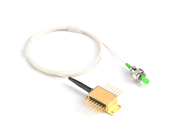
FIRSOL ITU Grid DFB 14-Pin Butterfly Laser Diodes combine a high-performance DFB laser chip with an integrated TEC, thermistor, monitor photodiode, and optical isolator in a hermetically sealed butterfly package.
Multiple optical output powers, SM and PM fiber options, pigtail configurations, and connector types are available to support different DWDM, fiber-sensing, measurement, and laser-source applications.
To select the appropriate configuration, provide FIRSOL with the required ITU channel or center frequency, output power, fiber type, pigtail length, connector, and pin configuration.
Frequently Asked Questions
Is every 1550 nm DFB laser ITU-grid compliant?
No. “1550 nm” is an approximate wavelength description. ITU-grid compliance requires the laser frequency or wavelength to match a defined channel within the specified tolerance.
Does a 14-pin butterfly laser need a TEC controller?
If the package contains a TEC, a compatible TEC controller is required to regulate its temperature. A laser diode current driver and a TEC controller perform different functions.
Does single-mode fiber maintain polarization?
Standard SM fiber maintains a single spatial mode but does not guarantee a stable polarization state. PM fiber should be selected when polarization must be preserved.
Is linewidth the same as wavelength stability?
No. Linewidth describes the width of the emitted optical spectrum. Wavelength stability describes changes in the center wavelength over temperature, current, time, or other operating conditions.
Are all 14-pin butterfly pinouts interchangeable?
No. Pin assignments can vary between package types and manufacturers. Always verify the pin diagram before connecting the device.
Conclusion
DFB 14-pin butterfly laser diodes provide a compact and reliable solution for applications requiring narrow linewidth, high SMSR, controlled wavelength, and fiber-coupled output.
The correct device should be selected by considering the complete system requirement—not only wavelength and power, but also linewidth, wavelength tolerance, SMSR, RIN, optical isolation, fiber type, PER, connector, pin configuration, and temperature-control requirements.
With the correct laser driver, TEC controller, optical interface, and thermal design, a DFB butterfly laser can provide stable long-term performance in demanding communication, sensing, spectroscopy, and measurement systems.