Polarization Maintaining Fiber Patch Cable: Working Principle, Specifications, Connectors & Applications
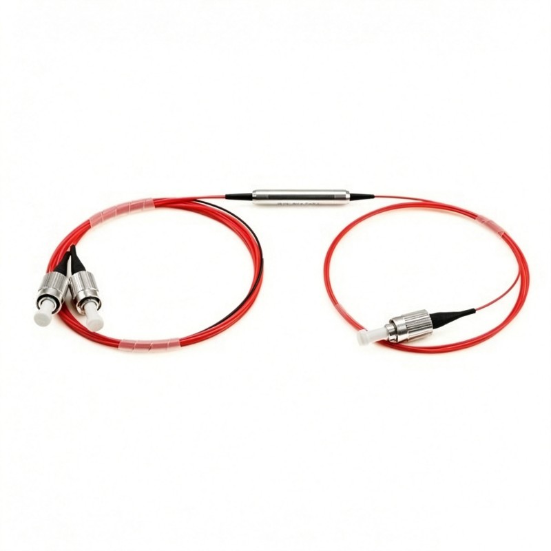
A polarization maintaining fiber patch cable, also known as a PM fiber patch cable or polarization maintaining patch cord, is a specialized fiber optic cable designed to preserve the linear polarization state of light when the input polarization is properly aligned with one of the fiber's principal axes.
Unlike conventional single mode fiber patch cables, polarization maintaining cables use highly birefringent optical fiber with two orthogonal principal axes: the slow axis and the fast axis. When linearly polarized light is launched along one of these axes, coupling into the orthogonal axis is minimized, allowing the polarization state to remain stable as the light propagates through the cable.
This capability makes PM fiber patch cables important in polarization-sensitive systems such as fiber optic sensors, interferometers, fiber lasers, optical amplifiers, gyroscopes, precision measurement systems, and advanced optical communication equipment.
However, selecting a PM patch cable involves more than simply choosing a wavelength and connector type. Fiber type, polarization extinction ratio, axis orientation, connector key alignment, insertion loss, return loss, optical power, cable construction, and operating environment can all affect system performance.
This guide explains how polarization maintaining fiber patch cables work, which specifications matter, and how to select the appropriate configuration for different optical systems.
What Is a Polarization Maintaining Fiber Patch Cable?
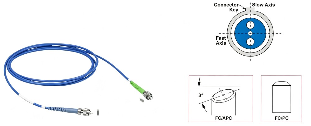
A polarization maintaining fiber patch cable is a connectorized optical fiber assembly made with polarization maintaining fiber.
Its primary purpose is not to create polarized light. Instead, it is designed to maintain an existing linear polarization state when the light is correctly launched into the PM fiber.
This distinction is important.
A standard single mode fiber can guide a single spatial mode, but it does not intentionally maintain a fixed relationship between two orthogonal polarization states. Environmental factors such as temperature variation, bending, mechanical stress, vibration, and fiber imperfections can cause polarization coupling.
PM fiber is designed differently. It introduces strong birefringence between two orthogonal polarization axes so that light launched along one principal axis is less likely to couple into the other.
A complete PM patch cable normally consists of:
PM optical fiber, precision fiber connectors, ferrules, strain-relief components, protective cable jackets or tubing, and accurately controlled fiber-axis-to-connector-key alignment.
For this reason, the assembly and alignment accuracy of a PM fiber patch cable are especially important.
How Does a Polarization Maintaining Fiber Patch Cable Work?
The operation of a PM fiber patch cable is based primarily on fiber birefringence.
Birefringence in Polarization Maintaining Fiber
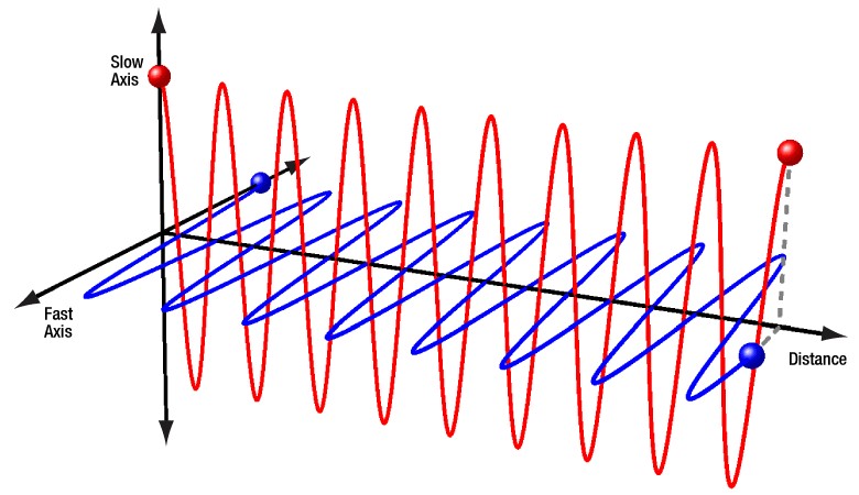
In an ideal circular optical fiber, two orthogonal polarization states could theoretically propagate with nearly identical effective refractive indices.
In a PM fiber, deliberate asymmetry is introduced into the fiber structure. This creates two principal polarization axes with different effective refractive indices.
They are generally referred to as:
Slow axis — the axis with the higher effective refractive index.
Fast axis — the orthogonal axis with the lower effective refractive index.
The birefringence can be expressed approximately as:
B = |nslow − nfast|
where nslow and nfast are the effective refractive indices associated with the two principal axes.
Because the two polarization modes propagate with different phase velocities, strong birefringence reduces unwanted coupling between them.
When linearly polarized light is accurately aligned with one of the principal axes, its energy remains predominantly associated with that axis as it propagates through the fiber.
This is the fundamental mechanism that allows polarization maintaining fiber to preserve linear polarization.
PANDA Fiber and Other PM Fiber Structures
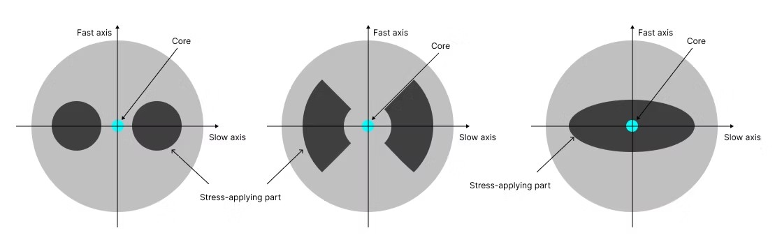
One of the best-known polarization maintaining fiber structures is PANDA fiber.
PANDA-type fiber contains stress-applying regions positioned on opposite sides of the optical core. These regions generate mechanical stress in the fiber and create strong birefringence between two orthogonal axes.
Other PM fiber structures also exist, so PANDA should not be treated as the only possible polarization-maintaining design.
From the user's point of view, the more important considerations are usually the fiber's operating wavelength, extinction ratio, attenuation, mode-field characteristics, axis orientation, and compatibility with the optical system.
Firsol's current PM fiber patch cable specifications cover fiber types including PM405, PM460, PM630, PM780, PM980, PM1300, PM1550, and PM1950 depending on the operating wavelength.
Slow Axis vs Fast Axis: Why Does It Matter?
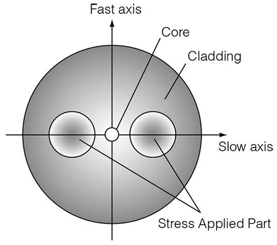
The slow and fast axes are fundamental to PM fiber operation.
If linearly polarized light is accurately launched along the slow axis, most of the optical power remains associated with that axis. The same principle applies when the system is intentionally designed to operate along the fast axis.
In many practical systems, the slow axis is used as the default reference axis.
Firsol PM fiber patch cables can be configured for:
Slow Axis, Fast Axis, or Both Axis, with the slow axis aligned to the connector key by default.
This information should always be confirmed when ordering a PM patch cable because two cables can have identical wavelength, connector, and length specifications but still be incompatible if their polarization-axis orientation is different.
Why Connector Key Alignment Is Critical
Connector alignment is one of the most important differences between a PM fiber patch cable and an ordinary fiber patch cable.
For a conventional single mode fiber connector, the rotational orientation of the fiber core is usually not critical because the fiber does not have a designated polarization axis that must be maintained relative to the connector key.
A PM fiber does.
During termination, the internal polarization axis of the fiber must be rotationally aligned with the mechanical key of the connector according to the required specification.
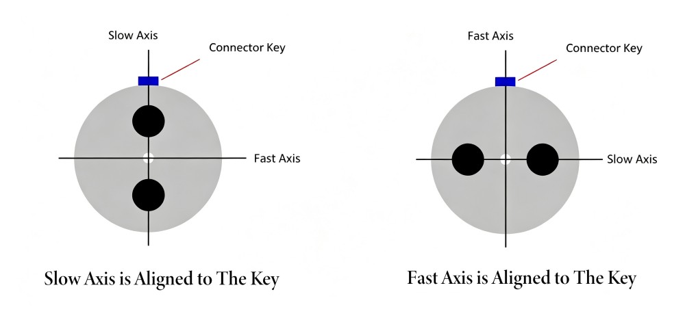
For example, when the specification states:
Slow Axis to Key
the slow axis of the PM fiber is aligned to the reference direction of the connector key.
If two PM components are connected together but their principal axes are rotationally misaligned, some optical power can couple from the intended polarization axis into the orthogonal axis. This reduces the effective polarization extinction ratio of the assembled optical system.
Therefore, connector selection alone is not enough.
When ordering a polarization maintaining patch cord, the required axis-to-key orientation should also be specified.
Polarization Maintaining Fiber Patch Cable vs Standard Single Mode Patch Cable
The two cable types may look similar externally, but they serve different purposes.
Parameter | Polarization Maintaining Fiber Patch Cable | |
|---|---|---|
Primary purpose | Maintain linear polarization | Transmit single-mode optical signals |
Fiber structure | High-birefringence PM fiber | Conventional single mode fiber |
Principal axes | Slow axis and fast axis | No defined PM slow/fast axes |
Polarization stability | Designed to minimize polarization coupling | Polarization can vary during propagation |
Connector rotational alignment | Critical | Usually not polarization-critical |
Key performance parameter | Extinction ratio / PER, IL, RL | Primarily IL and RL |
Typical applications | Sensors, interferometers, lasers, gyroscopes, polarization-sensitive optics | Telecom, data transmission, general fiber links |
This difference also explains why a PM fiber patch cable normally requires more precise termination and testing than a standard single mode patch cable.
Important Specifications of a PM Fiber Patch Cable
A PM cable should not be selected by wavelength alone. Several specifications directly affect its suitability for a system.
1. Insertion Loss
Insertion loss (IL) represents the optical power lost as light passes through the patch cable and its connectors.
It is normally expressed in decibels:
IL = 10 log₁₀(Pin / Pout)
Lower insertion loss means that more optical power reaches the output.
Insertion loss can be influenced by fiber characteristics, connector end-face quality, core alignment, fiber-to-ferrule alignment, connector mating conditions, wavelength, and manufacturing quality.
Firsol's specified maximum IL varies with operating wavelength. For example, it is ≤0.5 dB for the 1310 nm and 1480/1550 nm configurations, while shorter-wavelength versions have different limits.
2. Return Loss
Return loss describes how much optical power is reflected back toward the source.
Higher return loss generally means lower back reflection.
Firsol specifies:
UPC: ≥50 dB
APC: ≥60 dB
for its polarization maintaining fiber patch cable series.
APC connectors are therefore often selected for systems where minimizing optical back reflection is particularly important.
It is worth separating this from polarization performance: APC polishing can improve reflection performance, but connector polish alone does not determine the polarization extinction ratio of the PM cable.
3. Polarization Extinction Ratio
Polarization extinction ratio, often shortened to PER or simply ER, is one of the most important specifications for a PM patch cable.
It indicates how effectively the optical power remains in the intended polarization axis relative to the orthogonal axis.
It can be represented as:
ER = 10 log₁₀(Pdesired / Porthogonal)
A higher value indicates better polarization isolation.
The actual system extinction ratio can depend on more than the cable itself. Launch alignment, mating adapters, optical components, connector rotation, mechanical stress, and other elements in the optical path can all influence the measured system performance.
Firsol specifies different minimum extinction ratios depending on wavelength, ranging from ≥15 dB for the 405 nm configuration up to ≥23 dB for several telecom-band configurations.
4. Working Axis
The PM cable must match the axis requirement of the optical system.
Common configurations include:
Slow-axis operation, fast-axis operation, and both-axis configuration.
For Firsol PM patch cables, slow-axis-to-key alignment is the default unless another alignment is specified.
This information should be included in the purchase specification rather than assumed.
5. Maximum Optical Power
The acceptable optical power varies with wavelength and cable construction.
According to Firsol's current specification, maximum CW power ranges from 100 mW to 500 mW depending on the wavelength configuration.
For higher-power fiber laser or amplifier applications, optical power should therefore be checked explicitly rather than assuming that every PM patch cable supports the same power level.
Wavelength Options and PM Fiber Selection
One of the advantages of polarization maintaining fiber technology is that different PM fibers can be optimized for different spectral regions.
Firsol currently specifies PM fiber patch cables from 405 nm through 2000 nm.
Center Wavelength | Fiber Type | Max. Insertion Loss | Min. Extinction Ratio | Max. CW Power |
|---|---|---|---|---|
405 nm | PM405 | ≤2.5 dB | ≥15 dB | 100 mW |
488 nm | PM460 | ≤2.5 dB | ≥18 dB | 100 mW |
630 / 670 nm | PM630 | ≤1.5 dB | ≥20 dB | 100 mW |
780 / 850 nm | PM780 | ≤1.0 dB | ≥20 dB | 300 mW |
980 / 1064 nm | PM980 | ≤0.7 dB | ≥22 dB | 300 mW |
1310 nm | PM1300 | ≤0.5 dB | ≥23 dB | 500 mW |
1480 / 1550 nm | PM1550 | ≤0.5 dB | ≥23 dB | 500 mW |
1950 / 2000 nm | PM1950 | ≤0.5 dB | ≥20 dB | 500 mW |
These values are from the current Firsol Polarization Maintaining Fiber Patch Cable specification and are tested at 25°C.
The operating wavelength should normally be one of the first parameters selected because it determines the appropriate PM fiber family and can affect insertion loss, extinction ratio, optical power handling, and compatibility with other optical components.
For example, a 1550nm Polarization Maintaining Fiber Patch Cable is commonly selected for systems operating around the telecom C-band, while a 1064nm Polarization Maintaining Fiber Patch Cable is better suited to optical systems designed around 1064 nm sources.
Likewise, 780 nm, 850 nm, 980 nm, 1310 nm, and other wavelength-specific PM cables should be selected according to the actual operating wavelength rather than simply choosing the closest available fiber.
Connector Options for Polarization Maintaining Patch Cables
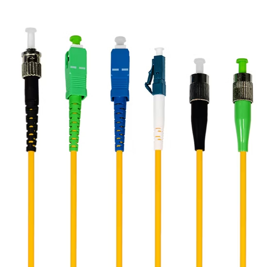
The connector must satisfy both the optical and mechanical requirements of the system.
Firsol's ordering options currently include:
FC/UPC, FC/APC, LC/UPC, LC/APC, SC/UPC, SC/APC, ST/UPC, ST/APC, E2000/UPC, and E2000/APC configurations.
FC/UPC and FC/APC
FC connectors are widely used in precision optical systems because their threaded coupling mechanism provides a stable mechanical connection.
For PM applications, the connector key also provides a useful rotational reference for aligning the internal polarization axis.
FC/APC is often selected where back reflection needs to be minimized, while FC/UPC may be suitable when an ultra-low-reflection APC interface is not required.
LC and SC Connectors
PM fiber patch cables can also be terminated with LC or SC connectors when required by the system interface.
The key issue remains the same: the PM fiber axis must be terminated and aligned according to the required orientation.
Connector type should therefore be selected together with:
wavelength, polish type, axis orientation, fiber type, and mating interface.
Hybrid PM Fiber Patch Cables
The two ends of a PM patch cable do not necessarily need to use identical connectors.
For example, a system may require:
FC/APC to LC/APC, FC/UPC to FC/APC, LC/UPC to SC/UPC, or another hybrid configuration.
When specifying a hybrid polarization maintaining patch cord, both connector types and the polarization-axis orientation at each end should be clearly defined.
Cable Diameter, Jacket and Length Options
Mechanical construction can be just as important as optical performance.
According to the Firsol ordering information, available constructions include:
250 μm bare fiber, 900 μm loose tube, 2.0 mm cable, and 3.0 mm cable, together with PVC or LSZH jacket options and configurable fiber lengths.
A 250 μm or 900 μm construction may be appropriate for compact optical assemblies and internal equipment routing, while 2.0 mm or 3.0 mm jacketed cables provide additional mechanical protection for general laboratory or system interconnections.
Cable length should also be selected carefully.
Longer fiber lengths may be necessary for equipment layout, but excessive fiber should not be tightly coiled or mechanically stressed simply to accommodate unused cable.
How to Choose the Right Polarization Maintaining Fiber Patch Cable
A practical selection process begins with the optical system rather than the connector.
First, identify the operating wavelength and select a PM fiber designed for that spectral region. Next, determine whether the equipment requires slow-axis, fast-axis, or another defined polarization orientation.
After that, select the required connector types and polish, such as FC/APC, FC/UPC, LC/APC, or another configuration.
The required extinction ratio should then be compared with the cable specification. Precision interferometric or polarization-sensitive measurement systems may place greater emphasis on ER than less demanding applications.
Insertion loss and return loss should also be considered together with optical power. A low insertion-loss cable may still be unsuitable if its power rating, axis orientation, or connector interface does not match the system.
Finally, specify the mechanical configuration: fiber length, cable diameter, jacket material, and any special connector or hybrid requirements.
A complete PM cable purchase specification may therefore look like:
1550 nm / PM1550 / Slow Axis to Key / FC/APC to FC/APC / 2 m / 2.0 mm LSZH
This is much more precise than requesting only a "1550 nm PM patch cable."
Typical Applications of Polarization Maintaining Fiber Patch Cables
PM fiber patch cables are used whenever polarization stability has a meaningful effect on system performance.
Fiber Optic Sensors
Many fiber sensors measure extremely small changes in phase, intensity, wavelength, or polarization. Uncontrolled polarization changes can introduce measurement uncertainty, so PM fiber is often used to improve polarization stability.
Fiber Optic Gyroscopes
Fiber optic gyroscopes rely on highly stable interference effects. Controlling polarization is therefore important for maintaining measurement accuracy and reducing polarization-related errors.
Optical Interferometers
Interferometric systems depend on stable phase relationships between optical signals. Polarization mismatch between the interfering beams can reduce fringe visibility and degrade measurement performance.
Fiber Lasers and Amplifiers
Some fiber laser and optical amplifier architectures contain polarization-sensitive components or require a defined polarization state. PM patch cables can provide stable interconnections between these components.
Optical Communications
Certain coherent, modulation, measurement, and test systems require controlled polarization states, making PM fiber useful in specialized communication equipment.
Polarization-Sensitive Optical Components
PM patch cables are also used to connect devices such as modulators, polarizers, interferometric components, polarization-sensitive detectors, and other optical components whose performance depends on polarization orientation.
The original Firsol specification also identifies fiber sensors, fiber amplifiers, optical communications, and polarization-sensitive components as representative applications.
Common Mistakes When Using PM Fiber Patch Cables
Even a high-quality PM patch cable can perform poorly when used incorrectly.
One common mistake is assuming that PM fiber automatically polarizes unpolarized light. It does not. The input polarization must be properly prepared and aligned with the required principal axis.
Another common issue is axis misalignment. If the polarization direction of the source, patch cable, and downstream component do not match, the system extinction ratio can deteriorate.
Connector contamination is another source of problems. Dust, oil, or debris on the ferrule end face can increase insertion loss and back reflection and can make troubleshooting difficult.
Incorrectly mating UPC and APC connectors should also be avoided. Although the connector families may appear mechanically similar in some situations, their end-face geometries are different.
Mechanical handling matters as well. Excessive bending, twisting, pulling, or external stress can affect optical performance and should be minimized.
Finally, system designers should distinguish between cable-level ER and system-level ER. The final performance depends on the complete optical chain, including the source polarization, connectors, adapters, PM fibers, modulators, polarizers, and other components.
Frequently Asked Questions
What is a polarization maintaining fiber patch cable?
A polarization maintaining fiber patch cable is a connectorized PM fiber assembly designed to preserve linear polarization when light is correctly launched along one of the fiber's principal axes.
Is PM fiber the same as polarizing fiber?
No.
A polarization maintaining fiber is primarily designed to maintain a polarization state that has already been launched correctly into the fiber.
A polarizing fiber, by contrast, is designed to preferentially transmit one polarization state while strongly attenuating another.
The terms should not be used interchangeably.
What is the difference between the slow axis and fast axis?
The slow and fast axes are two orthogonal principal polarization axes in a birefringent PM fiber.
The slow axis has a higher effective refractive index, while the fast axis has a lower effective refractive index.
Light aligned with one of these axes experiences reduced coupling into the other axis compared with propagation in conventional single mode fiber.
Why is the connector key important on a PM fiber patch cable?
The connector key provides a mechanical reference for the orientation of the internal PM fiber axes.
For example, Firsol uses slow axis aligned to the key by default.
Correct key orientation helps maintain consistent polarization alignment when the cable is connected to compatible PM optical equipment.
What is polarization extinction ratio?
Polarization extinction ratio indicates the ratio between optical power in the desired polarization axis and optical power coupled into the orthogonal polarization axis.
A higher ER generally indicates better preservation of the intended linear polarization state.
Should I choose FC/APC or FC/UPC for a PM fiber patch cable?
The choice depends primarily on the optical system.
FC/APC typically provides lower back reflection and higher return loss, while FC/UPC may be appropriate where an APC interface is not required.
According to the Firsol specification, return loss is ≥50 dB for UPC and ≥60 dB for APC.
The connector must also match the mating component and required polarization-axis orientation.
Can PM fiber patch cables use LC or SC connectors?
Yes.
PM fiber patch cables can be terminated with LC, SC, FC, ST, E2000, and other compatible connector configurations when the required fiber-axis alignment can be controlled during termination.
Firsol's current ordering options include multiple UPC and APC configurations for these connector families.
How do I choose between 780 nm, 980 nm, 1064 nm, 1310 nm and 1550 nm PM fiber?
Select the PM fiber according to the operating wavelength of the optical source and system.
For example, Firsol specifies PM780 for 780/850 nm, PM980 for 980/1064 nm, PM1300 for 1310 nm, and PM1550 for 1480/1550 nm operation.
Using the correct wavelength-optimized fiber helps achieve the specified insertion loss and polarization performance.
Custom Polarization Maintaining Fiber Patch Cables
Firsol provides Polarization Maintaining Fiber Patch Cables covering operating wavelengths from 405 nm to 2000 nm, with configurable PM fiber types, working axes, fiber lengths, cable diameters, jacket materials, and connector configurations.
Available connector options include FC, LC, SC, ST, and E2000 with UPC or APC polishing, while slow-axis, fast-axis, or both-axis configurations can be supplied according to system requirements.
For a custom PM fiber patch cable, provide the required operating wavelength, fiber type, connector configuration, cable length, jacket diameter, and polarization-axis orientation when requesting a quotation.