In-Line Manual Variable Optical Attenuator (VOA): How It Works & How to Choose
An in-line manual variable optical attenuator, often called a manual VOA, is a fiber optic device used to continuously reduce optical power to a required level. Unlike a fixed optical attenuator that provides a predetermined loss such as 5 dB or 10 dB, a manual VOA allows users to adjust attenuation according to the requirements of a test setup or optical system.
Manual variable optical attenuators are widely used in fiber optic testing, receiver sensitivity measurements, optical power calibration, component characterization, fiber laser systems, sensing, and laboratory experiments.
Because they are mechanically adjusted, manual VOAs normally do not require electrical power or an external controller. This makes them a simple and flexible solution when optical power needs to be adjusted manually rather than dynamically controlled.
This guide explains how an in-line manual VOA works, the specifications that matter most, the differences between single mode, multimode, and polarization-maintaining versions, and how to select the correct device for an optical system.
What Is an In-Line Manual Variable Optical Attenuator?
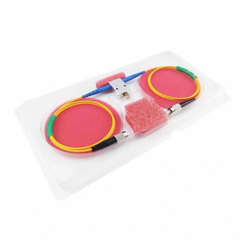
A variable optical attenuator (VOA) intentionally reduces the optical power transmitted through a fiber while allowing the attenuation level to be changed.
An in-line manual VOA has three main characteristics:
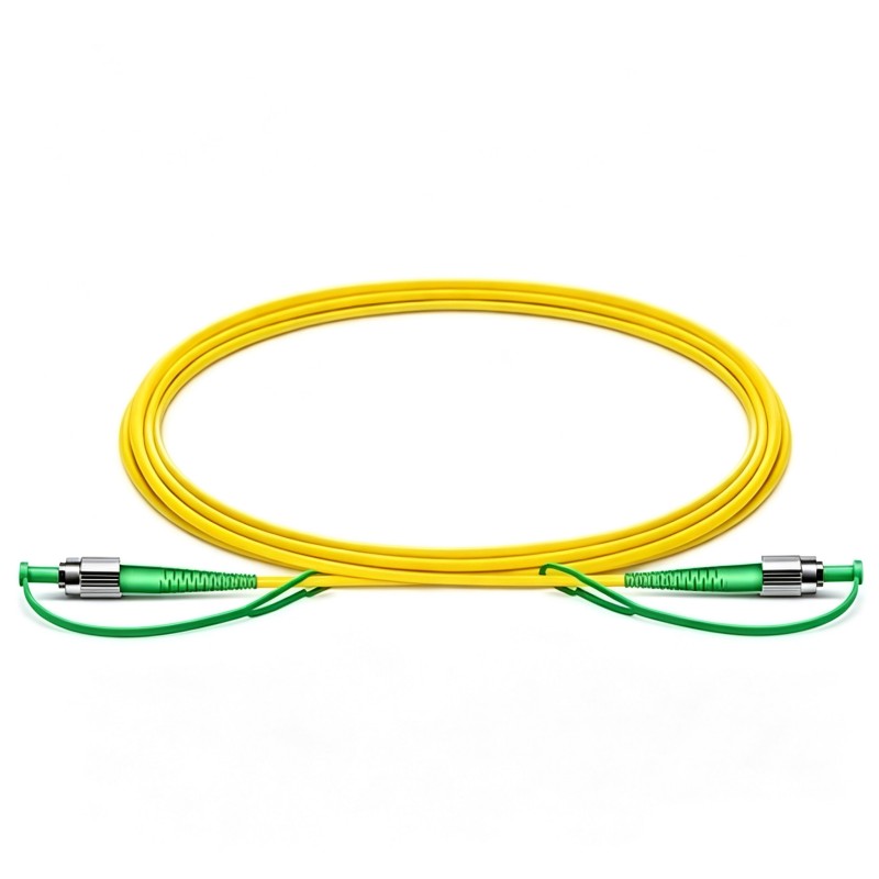
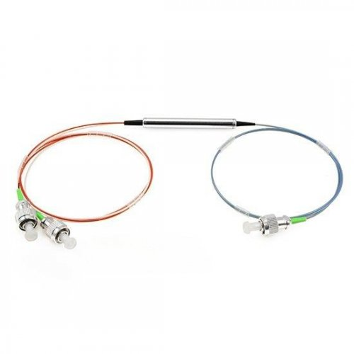
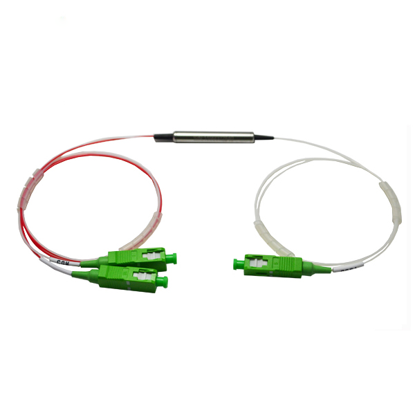
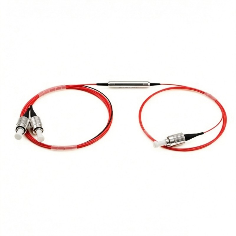
In-line: The attenuator is installed directly in the fiber path, typically with fiber pigtails on both ends. It can be supplied with bare fiber or terminated with connectors such as LC, SC, FC, or ST.
Manual: Attenuation is changed mechanically by the user, typically through an adjustment screw or similar mechanism.
Variable: Unlike a fixed attenuator, the amount of optical loss can be changed over a specified attenuation range.
For example, instead of installing separate 5 dB, 10 dB, and 20 dB fixed attenuators during testing, a manual VOA can be adjusted to different attenuation levels as required.
This makes it particularly useful for optical laboratories, production testing, R&D, system calibration, and applications where the required optical power changes during setup or measurement.
How Does a Manual VOA Work?
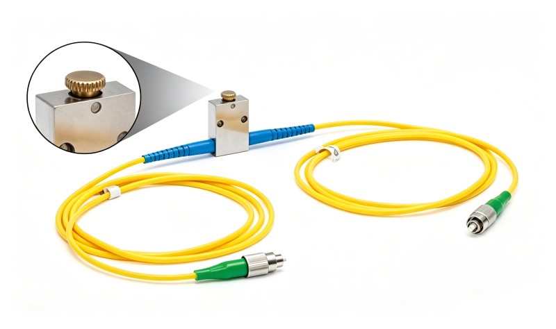
The basic optical path can be represented as:
Input Fiber → Adjustable Attenuation Mechanism → Output Fiber
Light enters through the input fiber and passes through an internal attenuation mechanism before reaching the output fiber.
When the adjustment screw is turned, the internal optical condition changes, increasing or decreasing the amount of optical power transmitted through the device.
In simple terms:
Higher attenuation → Lower output optical power
Lower attenuation → Higher output optical power
The attenuation is normally expressed in decibels:
Attenuation (dB) = 10 × log10 (Pin / Pout)
where:
Pin is the input optical power.
Pout is the output optical power.
For example, 10 dB of attenuation reduces the optical power to approximately 10% of the input level. If 10 mW enters the VOA, approximately 1 mW remains after 10 dB attenuation, excluding other system losses.
Because the adjustment is mechanical, an in-line manual variable optical attenuator does not normally require an electrical driver. This distinguishes it from electronically controlled VOAs such as MEMS attenuators.
Key Specifications of a Manual Variable Optical Attenuator
Choosing a VOA based only on its attenuation range is not sufficient. The operating wavelength, fiber type, insertion loss, return loss, optical power handling, and polarization characteristics should all be considered.
Operating Wavelength
The VOA should be optimized for the wavelength used in the optical system.
Common manual VOA wavelengths include:
532 nm
630 nm
670 nm
780 nm
850 nm
980 nm
1030 nm
1064 nm
1310 nm
1480 nm
1550 nm
A 1550 nm VOA, for example, should not automatically be assumed to provide the same optical performance at 1064 nm or 850 nm.
Different wavelengths may require different fiber types and internal optical configurations, so the specified operating wavelength range should always be checked.
Attenuation Range
The attenuation range indicates how much optical loss can be adjusted.
A specification such as:
0.5–60 dB
means that the VOA can provide adjustable attenuation over approximately that range under its specified operating conditions.
A wider attenuation range is particularly useful for receiver testing and laboratory measurements where optical power needs to be changed over several orders of magnitude.
However, attenuation range should not be confused with insertion loss.
Insertion Loss
Insertion loss is the baseline optical loss introduced when the VOA is inserted into the fiber link.
For example, a VOA may have:
Insertion Loss: ≤0.5 dB
Attenuation Range: 0.5–60 dB
These are different specifications.
Insertion loss is an unavoidable loss associated with the component itself, while variable attenuation is intentionally introduced by adjusting the device.
For systems with a limited optical power budget, lower insertion loss is generally preferable.
Return Loss
Return loss indicates how much light is reflected back toward the optical source.
Higher return loss generally means lower back reflection.
This can be important when working with:
Fiber lasers
Narrow-linewidth lasers
Interferometric systems
Precision optical measurements
Reflection-sensitive sources
Connector type also affects return loss. APC connectors are commonly selected when lower back reflection is required.
Polarization Dependent Loss
For standard single mode systems, polarization dependent loss (PDL) indicates how much the attenuation changes when the input polarization state changes.
Low PDL is desirable when the polarization of the incoming light is not controlled.
For polarization-maintaining systems, other parameters such as extinction ratio and fiber axis orientation become more important.
Maximum Optical Power
The maximum optical power rating should be checked before connecting the VOA to a laser or amplified optical system.
Importantly, the rating should be compared with the input power entering the VOA, not only the attenuated output power.
If 500 mW enters the attenuator and the output is reduced to 50 mW, the device still receives 500 mW at its input.
Applications involving fiber lasers or higher optical powers therefore require particular attention to the VOA's power-handling capability.
Single Mode vs Multimode vs Polarization-Maintaining Manual VOA
The VOA fiber type should normally match the fiber used in the optical system.
Feature | Single Mode VOA | Multimode VOA | PM VOA |
|---|---|---|---|
Fiber Type | Single mode fiber | Multimode fiber | Polarization-maintaining fiber |
Main Requirement | Low loss and stable attenuation | Match multimode fiber type | Preserve polarization |
Common Applications | Telecom, lasers, sensing | Multimode testing | Fiber lasers, sensing, interferometry |
Important Parameters | IL, RL, PDL | IL, attenuation range | IL, ER, axis alignment |
Single Mode Variable Optical Attenuator
A single mode variable optical attenuator is used with single mode fiber systems.
Typical applications include telecom networks, fiber lasers, optical sensing, component testing, and research systems.
Single mode VOAs are commonly available at wavelengths such as 980 nm, 1030 nm, 1064 nm, 1310 nm, 1480 nm, and 1550 nm.
The correct fiber should be selected according to the operating wavelength rather than simply using the same single mode fiber for every wavelength.
Multimode Variable Optical Attenuator
A multimode variable optical attenuator is designed for multimode fiber systems.
For example, an 850 nm multimode system may use OM1, OM2, OM3, or OM4 fiber depending on the application.
Because multimode fibers support multiple propagation modes and use larger core diameters than single mode fiber, a single mode VOA should not simply be substituted for a multimode version.
Multimode VOAs are commonly used for optical transceiver testing, link simulation, receiver testing, and laboratory power adjustment.
Polarization-Maintaining Variable Optical Attenuator
A polarization-maintaining variable optical attenuator, or PM VOA, is designed for applications where the polarization state must be preserved.
Typical applications include:
Fiber lasers
Interferometers
Fiber optic sensors
Coherent systems
Polarization-sensitive measurements
Important parameters may include the PM fiber type, extinction ratio, slow-axis or fast-axis operation, and connector key alignment.
When using connectorized PM components, the fiber axis orientation should be confirmed to ensure correct system integration.
Manual VOA vs MEMS Variable Optical Attenuator
Both devices perform variable optical attenuation, but their control methods are different.
Feature | Manual VOA | MEMS VOA |
|---|---|---|
Adjustment | Mechanical | Electrical |
External Power | Not required | Required |
Remote Control | No | Yes |
Automation | No | Yes |
System Complexity | Low | Higher |
Typical Application | Laboratory and manual testing | Automated systems |
A manual VOA is normally the better choice when attenuation is adjusted occasionally by an operator and electronic control is unnecessary.
A MEMS variable optical attenuator is more suitable when attenuation must be remotely controlled, automatically changed, or integrated into an electronic test or optical control system.
For example, a laboratory engineer manually setting optical power before taking measurements may prefer a manual VOA. An automated production test system that changes attenuation repeatedly under software control would generally benefit from a MEMS VOA.
How to Choose the Right Manual VOA
A practical way to select an in-line manual variable optical attenuator is to follow five main steps.
1. Identify the Operating Wavelength
Start with the optical source.
A 1550 nm telecom system, 1064 nm laser system, and 850 nm multimode system normally require different VOA configurations.
The VOA's specified wavelength range should cover the actual operating wavelength.
2. Match the Fiber Type
Determine whether the system uses:
Single mode fiber
Multimode fiber
Polarization-maintaining fiber
Matching the fiber type helps minimize unnecessary coupling loss and ensures that the VOA behaves correctly in the optical system.
3. Determine the Required Attenuation Range
Consider the minimum and maximum optical power that the system needs to produce or simulate.
Receiver sensitivity testing may require a large attenuation range, while basic power trimming may require much less.
4. Check Optical Power Handling
Make sure the optical power entering the VOA remains below the device's specified maximum optical power.
This is especially important in fiber laser, amplifier, and high-power test applications.
5. Select the Connector and Pigtail Configuration
The VOA should match the physical interface of the existing optical system.
Common connector options include:
LC/UPC and LC/APC
SC/UPC and SC/APC
FC/UPC and FC/APC
ST/UPC
Pigtail length and fiber protection should also be selected according to the installation environment.
Bare or 900 μm fiber may be suitable for integration inside equipment, while 2.0 mm or 3.0 mm cable provides greater mechanical protection for laboratory use.
Common Applications of Manual Variable Optical Attenuators
Manual VOAs are used whenever controllable optical loss is needed without electronic automation.
Common applications include:
Receiver sensitivity testing: Gradually reduce the received optical power to determine the sensitivity limit of an optical receiver or transceiver.
Optical link loss simulation: Introduce controlled attenuation to simulate different fiber link losses without changing the physical fiber length.
Component testing: Control the input optical power when evaluating detectors, optical switches, amplifiers, circulators, WDM devices, and other fiber optic components.
Instrument protection: Reduce excessive optical power before it reaches sensitive detectors, power meters, or measurement instruments.
System calibration: Produce different optical power levels during calibration and verification.
Fiber laser and research systems: Provide manual optical power adjustment at wavelengths such as 980 nm, 1030 nm, and 1064 nm.
Frequently Asked Questions
What is the difference between a fixed optical attenuator and a manual VOA?
A fixed optical attenuator provides one predetermined attenuation value. A manual VOA allows the attenuation to be changed continuously over a specified range.
Fixed attenuators are useful when the required loss is already known, while manual VOAs are more flexible for testing, calibration, and laboratory use.
Does a manual variable optical attenuator require power?
No. A manual VOA normally uses mechanical adjustment and does not require electrical power or an external controller.
Can a 1550 nm VOA be used at 1310 nm?
Only if the device is specifically designed and specified for both wavelengths.
A VOA optimized only for 1550 nm should not automatically be assumed to provide the same insertion loss, attenuation accuracy, or other performance at 1310 nm.
Can a single mode VOA be used in a multimode system?
It is generally not recommended. Single mode and multimode fibers have different core sizes and propagation characteristics.
For reliable performance, the VOA fiber type should match the fiber system.
When should I use a PM variable optical attenuator?
Use a PM VOA when maintaining a defined polarization state is important, such as in fiber lasers, interferometers, sensing systems, and polarization-sensitive measurements.
Manual VOA or MEMS VOA: which should I choose?
Choose a manual VOA when simple, occasional manual adjustment is sufficient.
Choose a MEMS VOA when the attenuation must be controlled electronically, remotely, or automatically.
In-Line Manual Variable Optical Attenuators from Firsol
Firsol provides in-line manual variable optical attenuators for telecom, fiber laser, optical sensing, laboratory, test, and measurement applications.
Available configurations include multiple operating wavelengths and different:
Single mode, multimode, and polarization-maintaining fibers
Attenuation ranges
Optical power ratings
Fiber pigtail lengths
Cable diameters
LC, SC, FC, and ST connectors
UPC and APC connector interfaces
In addition to in-line manual VOAs, Firsol also offers other variable optical attenuator configurations for applications requiring different optical interfaces or electronic control.
When selecting a VOA, wavelength and attenuation range are only the starting point. Fiber type, insertion loss, return loss, optical power, polarization performance, and mechanical configuration should also be considered to ensure reliable operation in the complete optical system.
For custom wavelength, fiber, connector, pigtail, or other configuration requirements, contact Firsol for a suitable variable optical attenuator solution.