What Is a 1×2 CWDM Filter? Working Principle, Specifications and Selection Guide
A 1×2 CWDM filter is a compact wavelength-selective optical component used to separate one CWDM wavelength from a multiwavelength signal or combine that wavelength with other optical channels. Unlike an optical splitter, which divides optical power without distinguishing between wavelengths, a CWDM filter routes light according to wavelength.
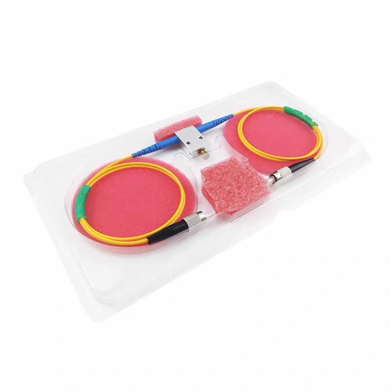
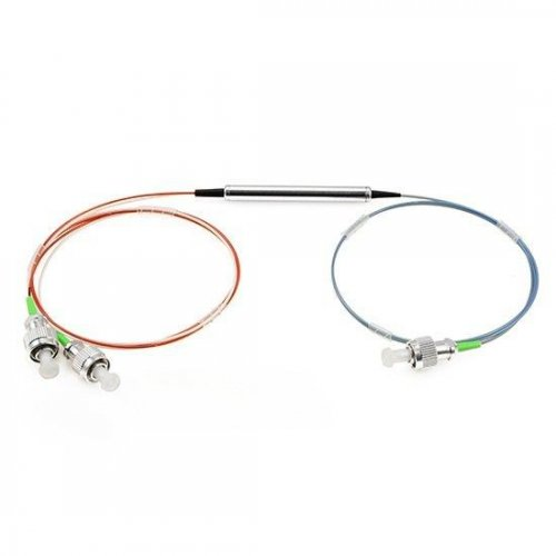
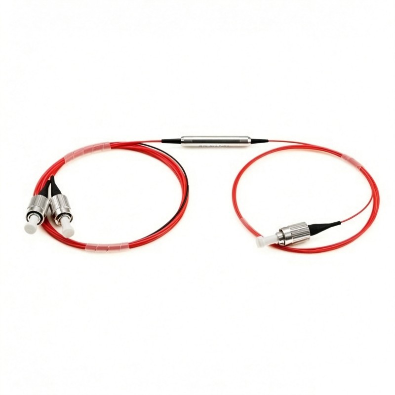
The device normally has three fiber ports: a common port, a pass port and a reflect port. Its simple three-port configuration makes it useful as a single-channel add/drop filter and as a basic building block for larger CWDM multiplexing and demultiplexing systems.
This article explains how a 1×2 CWDM filter works, what its three ports do, how to interpret its main specifications and how to select the right filter for an optical system.
What Does “1×2 CWDM Filter” Mean?
The product name contains three important terms:
1×2 describes a device with one common optical path and two wavelength-dependent output paths. In practice, the filter has three physical ports.
CWDM stands for Coarse Wavelength Division Multiplexing, a technology that carries multiple optical channels over the same fiber using widely spaced wavelengths.
Filter means that the component selects optical signals according to wavelength instead of dividing them according to a fixed power ratio.
A standard CWDM system uses channels spaced 20 nm apart. Typical nominal channel wavelengths include 1270, 1290, 1310, 1330 nm and subsequent channels up to 1610 nm.
It is important to understand that “20 nm” describes the spacing between adjacent CWDM channel center wavelengths. It does not mean that the filter has a 20 nm passband.
For example, a 1550 nm 1×2 CWDM filter is designed to transmit the selected 1550 nm channel through its pass port while directing wavelengths outside that channel to its reflect port.
The Three Ports of a 1×2 CWDM Filter
A typical 1×2 CWDM filter has the following ports:
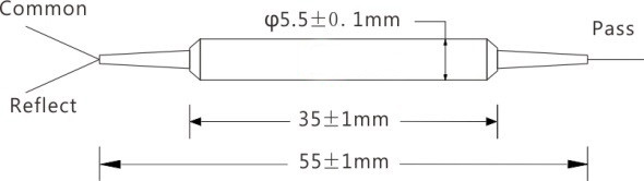
Common Port
The common port, usually marked COM, carries the combined optical signal. When the filter is used for demultiplexing, all input wavelengths enter through this port.
Pass Port
The pass port, sometimes marked PASS, T or Transmission, carries the selected CWDM channel. A 1550 nm filter, for example, routes the 1550 nm signal from the common port to the pass port.
Reflect Port
The reflect port, sometimes marked REFLECT, R or Reflection, carries the wavelengths outside the selected pass channel. These remaining wavelengths can continue through another CWDM filter in a cascaded system.
The basic demultiplexing path can be expressed as follows:
COM → PASS: selected CWDM wavelength
COM → REFLECT: remaining wavelengths
When used in the opposite direction, the filter can add the selected wavelength to the group of reflected wavelengths:
PASS + REFLECT → COM: combined multiwavelength signal
The exact port arrangement should always be confirmed from the manufacturer’s port diagram because fiber colors and labels may differ between products.
How Does a 1×2 CWDM Filter Work?
Most compact 1×2 CWDM filters are based on thin-film filter technology, commonly abbreviated as TFF.
A thin-film filter consists of multiple dielectric layers deposited onto an optical substrate. The thickness and refractive index of these layers are carefully controlled so that a specific wavelength range is transmitted while wavelengths outside that range are reflected.
Inside a typical CWDM filter:
A multiwavelength signal enters the common port.
A collimating element converts the light from the input fiber into a controlled optical beam.
The beam reaches the thin-film filter.
The selected CWDM channel passes through the filter.
The remaining wavelengths are reflected.
The transmitted and reflected signals are coupled into their corresponding output fibers.
This wavelength-selective behavior allows the device to add or drop one channel without converting the optical signal into an electrical signal.
Because the filtering operation is passive, the device does not require a power supply or software configuration.
Multiplexing and Demultiplexing Functions
A 1×2 CWDM filter can perform two basic functions.
Demultiplexing or Dropping a Channel
When multiple wavelengths enter the common port, the designated CWDM wavelength exits through the pass port. The remaining wavelengths exit through the reflect port.
For example, if a signal containing 1510, 1530, 1550 and 1570 nm enters a 1550 nm filter:
1550 nm is directed to the pass port.
1510, 1530 and 1570 nm are directed to the reflect port.
This operation is commonly called dropping the 1550 nm channel.
Multiplexing or Adding a Channel
When the optical direction is reversed, a selected wavelength entering the pass port can be combined with other wavelengths entering the reflect path. The combined signal then leaves through the common port.
This operation is commonly called adding a channel.
Although a passive filter is generally optically reciprocal, system designers should still follow the specified port configuration and verify the required insertion loss and isolation in the intended direction.
Understanding 20 nm Channel Spacing
Channel spacing and channel passband are different specifications.
Channel spacing is the wavelength difference between the nominal center wavelengths of adjacent CWDM channels. For a standard 20 nm CWDM filter, adjacent channels may be 1510 and 1530 nm or 1530 and 1550 nm.
Channel passband is the wavelength range around the selected center wavelength over which the filter meets its specified transmission performance.
For example, a 20 nm CWDM filter may provide a channel passband of at least 13 nm at the −0.5 dB points. This gives the optical transmitter some wavelength tolerance while helping the filter reject adjacent channels.
A wider passband can be valuable when:
The laser wavelength changes with temperature.
Uncooled CWDM transceivers are used.
The system must operate across a wide temperature range.
Manufacturing tolerances cause small variations in transmitter wavelength.
Therefore, customers should not select a filter based only on its nominal wavelength. The passband must also accommodate the actual wavelength range of the optical source.
Key Specifications of a 1×2 CWDM Filter
Understanding the datasheet parameters is essential for correct system design.
Pass Channel Wavelength
This is the nominal center wavelength transmitted between the common and pass ports. Standard options typically cover CWDM channels from 1270 to 1610 nm.
Wavelength Accuracy
Wavelength accuracy indicates how closely the actual filter center wavelength matches its specified value. Accurate center-wavelength control helps maintain consistent transmission across the required passband.
Pass Channel Insertion Loss
Pass channel insertion loss is the optical power loss between the common port and the pass port at the selected channel.
Lower insertion loss means that more of the selected wavelength reaches the receiver. A typical compact single-mode filter may specify a maximum pass-channel insertion loss of approximately 0.6 dB before connectors are added.
Reflect Channel Insertion Loss
Reflect channel insertion loss is the loss experienced by wavelengths traveling between the common and reflect ports. Because the reflect path may pass through several cascaded filters, this parameter is especially important in a multichannel CWDM module.
A typical single-mode 1×2 CWDM filter may specify reflect-channel insertion loss of no more than approximately 0.4 dB, excluding connectors.
Pass Channel Isolation
Pass-channel isolation describes how effectively unwanted wavelengths are blocked from entering the pass port. Higher isolation reduces crosstalk between the selected channel and the remaining CWDM channels.
A pass-channel isolation value of 30 dB means that unwanted optical power is attenuated by at least 30 dB relative to the defined test condition.
Reflect Channel Isolation
Reflect-channel isolation indicates how effectively the selected wavelength is prevented from leaking into the reflect port. It is particularly relevant when the reflect port continues toward other receivers or filters.
Pass-channel and reflect-channel isolation are not necessarily equal because the filter performs different optical functions along the two paths.
Return Loss
Return loss represents the amount of light reflected back toward the source. Higher return loss is generally preferred, particularly in systems containing lasers or other reflection-sensitive components.
Connector polish also affects return loss. APC connectors are often selected when minimizing back reflection is important.
Directivity
Directivity indicates the isolation between optical ports that should not directly couple with each other. High directivity helps prevent unwanted signals from traveling between the pass and reflect branches.
Polarization-Dependent Loss
Polarization-dependent loss, or PDL, is the variation in insertion loss as the input state of polarization changes. Low PDL is important in standard single-mode systems where the polarization state may vary unpredictably.
Optical Power Handling
Maximum optical power specifies how much continuous-wave optical power the filter can safely handle. A standard compact CWDM filter may be rated for approximately 0.3 W, but higher-power applications require a specially designed component.
Operating Temperature
The operating temperature range defines the environment in which the filter is expected to meet its optical specifications. Both the filter package and the chosen fiber coating or cable structure must be suitable for the installation conditions.
Connector Loss Must Be Included in the Link Budget
Datasheet insertion-loss values are often measured without connectors. Adding connectors increases the total loss of the finished component.
For example, if the connector-free pass-channel loss is specified as 0.6 dB and connectors add approximately 0.3 dB, the expected maximum loss of the connectorized path may be around 0.9 dB, depending on how the manufacturer defines the added connector loss.
The complete optical budget should include:
CWDM filter insertion loss
Connector loss
Splice loss
Fiber attenuation
Loss from other passive components
Engineering margin
Possible aging and temperature effects
This becomes more important when several filters are cascaded because the reflect-path loss accumulates as wavelengths pass through successive devices.
Cascading 1×2 Filters into a CWDM Multiplexer
A single 1×2 filter adds or drops one wavelength. Multiple filters can be connected in series to build a multichannel CWDM multiplexer or demultiplexer.
In a demultiplexer, the first filter drops one wavelength from the common signal. Its reflect port sends the remaining wavelengths to the next filter, which drops another channel. The process continues until all required channels have been separated.
The order of filters affects the total insertion loss experienced by each channel. A wavelength dropped by the first filter passes through fewer reflect paths than a wavelength dropped by the final filter.
If the reflect-path insertion loss of each filter is 0.4 dB, a channel that passes through four preceding filters may accumulate approximately 1.6 dB of reflect-path loss before reaching its own pass filter. Its final pass-channel loss must then be added to this value.
For this reason, filter sequence, total channel count and link-budget margin should be considered together when designing a cascaded CWDM assembly.
Single-Mode and Polarization-Maintaining CWDM Filters
Both single-mode and polarization-maintaining 1×2 CWDM filters perform wavelength-selective add/drop functions, but they are designed for different polarization requirements.
Single-Mode 1×2 CWDM Filter
A standard single-mode version typically uses fiber such as SMF-28e. It is suitable when the polarization state does not need to be maintained through the component.
Important parameters include:
Pass- and reflect-channel insertion loss
Channel isolation
Polarization-dependent loss
Return loss
Directivity
These filters are commonly used in telecommunications, access networks, line monitoring and general-purpose CWDM systems.
Polarization-Maintaining 1×2 CWDM Filter
A polarization-maintaining CWDM filter uses PM fiber and controlled axis alignment to preserve linearly polarized light.
In addition to the normal CWDM specifications, the PM version includes parameters such as:
Polarization extinction ratio
Working axis
PM fiber type
Fiber-axis orientation
Connector-key alignment
For example, a PM CWDM filter may use PM1550 fiber, support both-axis operation and provide an extinction ratio of at least 20 dB. For a connectorized PM component, the fiber slow axis may be aligned with the connector key by default.
Connectors and fiber handling can reduce the measured extinction ratio. Therefore, the complete assembled component—not only the internal filter—must be considered when evaluating polarization performance.
PM CWDM filters are suitable for polarization-sensitive communication systems, fiber lasers, optical sensing, interferometry and test equipment.
1×2 CWDM Filter vs. Optical Splitter
A CWDM filter should not be confused with a 1×2 optical splitter.
Characteristic | 1×2 CWDM Filter | 1×2 Optical Splitter |
|---|---|---|
Routing principle | Wavelength-selective | Power division |
Output behavior | Different wavelengths use different ports | All wavelengths are divided between outputs |
Typical port labels | COM, PASS and REFLECT | Input, Output 1 and Output 2 |
Typical specification | Passband and channel isolation | Splitting ratio and uniformity |
Main application | Add/drop or wavelength multiplexing | Optical power distribution |
A splitter may divide an input signal in a 50/50 or 10/90 ratio, but it does not isolate one CWDM channel from another. A CWDM filter routes the selected wavelength to a specific port and therefore performs a different function.
Typical Applications
1×2 CWDM filters are widely used in:
CWDM add/drop links
Telecommunications networks
Metropolitan and access networks
Mobile fronthaul and backhaul
CATV transmission systems
Optical line-monitoring equipment
Security and surveillance networks
Data transmission over limited fiber infrastructure
Fiber-optic sensing systems
Laboratory and test setups
Polarization-sensitive optical systems when a PM version is used
A common application is adding a new service wavelength to an existing fiber without interrupting the wavelengths already carried by that fiber.
How to Select a 1×2 CWDM Filter
When requesting a quotation or configuring a CWDM filter, the following information should be provided.
1. Pass Channel Wavelength
Specify the CWDM channel to be added or dropped, such as 1310, 1470, 1550 or 1610 nm.
2. Channel Spacing and Passband
Confirm that the product uses 20 nm CWDM channel spacing and that its passband covers the transmitter’s full wavelength range.
3. Fiber Type
Choose standard single-mode fiber for polarization-insensitive systems or PM fiber when the polarization state must be preserved.
4. Working Axis
For a PM filter, specify whether the signal will operate on the slow axis, fast axis or whether both-axis operation is required.
5. Pigtail Construction
Common options include:
250 μm bare fiber
900 μm loose tube
Custom cable protection
Bare fiber is compact and suitable for integration into modules, while a loose tube provides more mechanical protection for handling and installation.
6. Pigtail Length
Typical lengths include 0.5, 1.0, 1.5 and 2.0 m. Custom lengths may also be requested.
7. Connector Type
Available connector configurations may include:
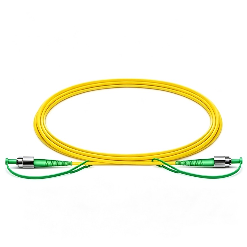
LC/UPC and LC/APC
SC/UPC and SC/APC
FC/UPC and FC/APC
ST/UPC and ST/APC
No connector
The connector type should match the system interface, return-loss requirement and polarization-axis requirement.
8. Optical Power
Confirm that the filter’s rated continuous-wave optical power is sufficient for the application. Standard 0.3 W devices should not automatically be used in higher-power laser systems.
9. Environmental Requirements
Check the operating and storage temperature ranges, especially for outdoor cabinets, industrial systems and temperature-sensitive measurement equipment.
10. Port Identification
Request a port diagram or confirm the fiber-color coding so that the COM, PASS and REFLECT fibers can be correctly connected during installation.
Common Questions About 1×2 CWDM Filters
Is 20 nm the passband of the filter?
No. It is the nominal spacing between adjacent CWDM channels. The actual passband is narrower and should be listed separately in the datasheet.
Can one filter separate all CWDM channels?
No. A single 1×2 filter normally separates one selected channel from the remaining wavelengths. Multiple filters or an integrated multichannel CWDM module are required to separate several channels individually.
Can a 1×2 CWDM filter work in both directions?
It can generally be used for adding or dropping a wavelength because the passive optical paths are reciprocal. However, the manufacturer’s port arrangement and specified optical performance should be followed.
Does a CWDM filter divide optical power like a coupler?
No. It routes signals according to wavelength. A coupler or splitter divides optical power according to a coupling ratio.
Do connectors affect filter performance?
Yes. Connectors add insertion loss and may reduce return loss. In PM filters, connectorization and axis alignment can also affect the extinction ratio.
Can a standard single-mode filter preserve polarization?
It may transmit polarized light, but it is not designed to maintain a defined polarization state. A polarization-maintaining CWDM filter should be used when polarization preservation is required.
Conclusion
A 1×2 CWDM filter is a compact passive component that adds or drops one optical wavelength from a multiwavelength fiber link. Its thin-film filter separates the selected pass channel from the reflected group of remaining wavelengths, allowing it to function as both a multiplexer and a demultiplexer.
Correct selection requires more than choosing a nominal wavelength. Engineers should also evaluate the passband, pass- and reflect-channel insertion loss, isolation, return loss, optical power, connector loss and environmental requirements. In cascaded systems, reflect-path losses and filter order must be included in the total link budget.
For conventional telecommunications and data transmission systems, a single-mode CWDM filter is normally appropriate. When the polarization state must be preserved, a polarization-maintaining version with a specified extinction ratio and fiber-axis alignment should be selected.