What Is an Optical Circulator? Working Principle, Types, Applications, and Selection Guide
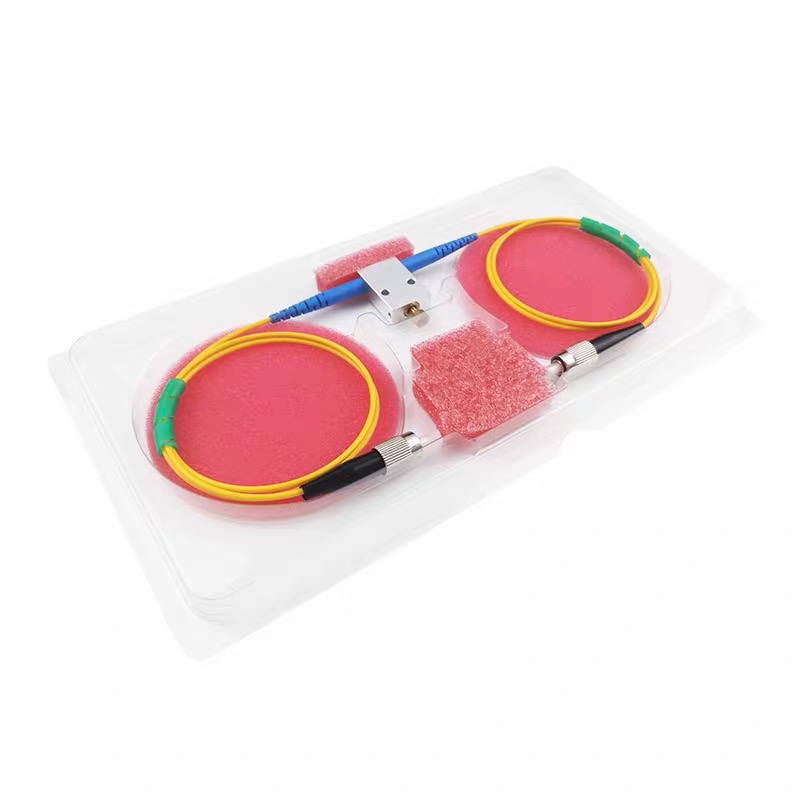
An optical circulator is a compact passive component that routes light from one fiber port to the next designated port while strongly suppressing undesired reverse transmission. In a commonly used three-port circulator, light entering Port 1 travels to Port 2, while light returning to Port 2 is directed to Port 3 instead of going back to Port 1.
This nonreciprocal routing is useful wherever forward- and backward-propagating signals must be separated, including bidirectional links, fiber Bragg grating systems, OTDR and sensing systems, fiber lasers, dispersion-compensation modules, and optical coherence tomography. This guide explains the operating principle, main types, critical specifications, applications, and selection process.
What Is an Optical Circulator?
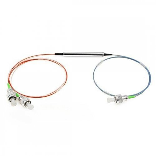
An optical circulator, also called a fiber optic circulator, is a nonreciprocal multiport optical device. “Nonreciprocal” means that reversing the direction of propagation does not cause light to retrace the same optical path.
For a typical three-port device, the specified low-loss paths are:
Port 1 → Port 2
Port 2 → Port 3
If a signal is launched into Port 1, it exits Port 2 with relatively low insertion loss. If that signal is reflected by a device connected to Port 2, the returning light reenters Port 2 and is routed to Port 3 rather than back toward the source at Port 1.
A coupler divides optical power according to a coupling ratio, whereas a circulator directs light according to the input port and propagation direction. Unlike an optical switch, a passive circulator normally requires no electrical control signal and does not alternate its route over time.
The term “unidirectional” does not mean that the connected fiber can carry light in only one direction. It means that the component has preferred sequential paths and high attenuation between undesired port combinations.
Important: Some ideal circulator diagrams show complete cyclic routing, such as 1 → 2, 2 → 3, and 3 → 1. However, many commercial three-port fiber circulators specify only the 1 → 2 and 2 → 3 operating paths. Always follow the port diagram and guaranteed specifications in the product datasheet.
How Does an Optical Circulator Work?
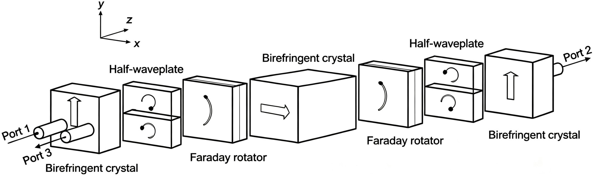
The operation of an optical circulator depends on a combination of polarization manipulation and the magneto-optic Faraday effect.
In a reciprocal optical element, reversing the propagation direction generally reverses the transformation produced during forward travel. A Faraday rotator behaves differently: under a magnetic field, it rotates polarization in a direction determined by that field, and backward propagation does not simply cancel the forward rotation. This nonreciprocal behavior makes directional routing possible.
A polarization-independent circulator commonly uses polarization beam splitters or birefringent crystals to separate an arbitrary input into two orthogonal polarization components. Faraday rotators, wave plates, prisms, and related elements rotate and redirect them before they are recombined into the required output fiber. Light entering from another port encounters these elements in a different sequence and is therefore directed toward a different output.
The internal arrangement varies with wavelength, polarization requirement, power, and package design. Some high-power designs use magneto-optic crystals such as terbium gallium garnet (TGG). Regardless of construction, desired paths should have low insertion loss and undesired paths high attenuation.
Three-Port vs. Four-Port Optical Circulators
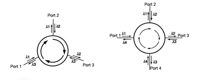
Three-Port Optical Circulator
The three-port configuration is the most common. Its primary paths are Port 1 → Port 2 and Port 2 → Port 3, making it suitable for separating transmitted and reflected light, working with an FBG, or sharing one fiber for transmit and receive functions. For example, a source at Port 1 can illuminate a reflective sensor through Port 2, while the returned signal is routed to a detector at Port 3.
Four-Port Optical Circulator
A four-port circulator adds another sequential path, commonly Port 3 → Port 4. Some designs also provide Port 4 → Port 1, while others do not specify it. Four-port devices support more complex routing, but the guaranteed paths and loss for each path must be confirmed.
Configuration | Common Specified Paths | Typical Uses |
|---|---|---|
3-port | 1 → 2, 2 → 3 | FBG systems, reflection monitoring, bidirectional links, sensing |
4-port | 1 → 2, 2 → 3, 3 → 4 | Multi-stage routing, advanced sensing, specialized network designs |
Main Types of Optical Circulators
Optical circulators can be classified by port count, polarization behavior, wavelength range, and power-handling capability.
Polarization-Independent Optical Circulators
A polarization-independent circulator accepts an input whose state of polarization is unknown or changing. Low polarization-dependent loss helps keep insertion loss stable, making this type suitable for telecommunications, general sensing, and standard single-mode test systems.
Polarization-Maintaining Optical Circulators
A polarization-maintaining (PM) circulator uses PM fiber and preserves a properly aligned input polarization. It is used in interferometry, coherent systems, fiber gyroscopes, fiber lasers, and precision sensors. Buyers should specify the PM fiber, working axis, connector-key orientation, and required polarization extinction ratio.
High-Power Optical Circulators
High-power circulators use suitable fibers, coatings, optical materials, and thermal designs for fiber lasers, amplifiers, pumping arrangements, and high-power testing. A CW rating cannot automatically be applied to a pulsed source with the same average power; pulse width, repetition rate, peak power, connector condition, and reflected power must also be reviewed.
Narrowband and Broadband Optical Circulators
Many circulators are optimized around a center wavelength such as 980, 1064, 1310, 1480, or 1550 nm. Broadband versions cover a wider band for sources such as those used in OCT, but their loss, isolation, PDL, and PMD must meet requirements across the complete source spectrum.
Key Optical Circulator Specifications
Understanding the datasheet is essential because two devices with the same center wavelength and port count can perform very differently.
Specification | What It Describes | Why It Matters |
|---|---|---|
Operating Wavelength/Bandwidth | Wavelength range over which performance is specified | A circulator used outside this range may have higher loss and lower isolation |
Insertion Loss | Power lost along a desired path, such as 1 → 2 | Directly affects the optical power budget |
Isolation | Suppression between an undesired reverse path, such as 2 → 1 | Protects the source and reduces backward crosstalk |
Directivity | Suppression of leakage between nonadjacent ports | Important when measuring weak returned signals |
Return Loss | Amount of light reflected back from a port | Higher return loss is preferable in reflection-sensitive systems |
PDL | Change in loss with input polarization | Especially important for polarization-independent devices |
PMD | Differential delay between polarization modes | Can affect broadband, high-speed, interferometric, and OCT systems |
PER | Ratio between desired and unwanted polarization components | A key specification for PM circulators |
Maximum Optical Power | Qualified CW and/or pulsed power level | Prevents optical or thermal damage |
Operating Temperature | Temperature range over which specifications apply | Important for field, industrial, and outdoor systems |
Evaluate insertion loss as a maximum value over the required wavelength and temperature range, and determine whether it includes connectors. Isolation, directivity, and return loss are all expressed in decibels but describe different leakage or reflection mechanisms; because port definitions can vary, compare the associated measurement diagrams rather than numbers alone.
Common Optical Circulator Applications
1. Bidirectional Transmission Over a Single Fiber
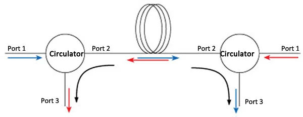
Circulators at both ends of a fiber can separate counter-propagating transmit and receive signals. Each routes its local transmitter into the line and directs the returning signal to the local receiver. This saves fiber, but the link budget must include circulator loss, reflections, Rayleigh backscattering, receiver sensitivity, and directional crosstalk.
2. FBG-Based Optical Add-Drop Multiplexing
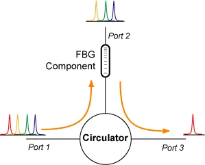
To drop a wavelength, a WDM signal travels from Port 1 through Port 2 to an FBG. The grating reflects its designed wavelength and passes the others. The reflected wavelength reenters Port 2 and exits Port 3. The FBG performs wavelength-selective reflection; the circulator separates and routes the reflected signal.
3. OTDR, Reflection Monitoring, and Fiber Sensors
A circulator allows a source and detector to share a sensing fiber without a power-splitting coupler. The test light travels from Port 1 to Port 2; backscattered or reflected light returns through Port 2 and exits Port 3 toward the detector. This arrangement is useful in OTDR, FBG interrogation, distributed sensing, reflective probes, and component testing. Low loss improves signal strength, while high directivity limits leakage into the detector.
4. Chromatic-Dispersion Compensation
A circulator and chirped FBG can form a reflective dispersion-compensation module. Different wavelengths experience different delays in the grating, and the reflected signal returns through the circulator to a separate output. The chirped FBG supplies the wavelength-dependent delay; the circulator only provides routing.
5. Fiber Lasers and Optical Amplifiers
Circulators can separate returned light and manage counter-propagating signals or bidirectional pumping in fiber lasers and amplifiers. High-power capability, wavelength compatibility, low loss, and reflected-power conditions are critical; polarization-sensitive systems may also require a PM circulator.
6. Optical Coherence Tomography
In OCT, a broadband circulator can route light toward a sample and direct the return toward the detector. Low insertion loss, PDL, PMD, and chromatic dispersion are important across the full source bandwidth. A narrowband telecom device may be unsuitable even if it has the same nominal center wavelength.
Optical Circulator vs. Optical Isolator
Optical circulators and optical isolators are both nonreciprocal components, but they handle backward light differently.
Feature | Optical Circulator | Optical Isolator |
|---|---|---|
Typical Port Count | Three or Four | Two |
Forward Light | Routed to the next port | Transmitted through the device |
Backward Light | Redirected to another port | Strongly attenuated or rejected |
Main Purpose | Separate and reuse counter-propagating or reflected signals | Protect a laser or amplifier from back reflections |
Typical Applications | FBG routing, sensing, bidirectional links, OCT | Laser protection, amplifier protection, reflection suppression |
A circulator can sometimes provide an isolator-like function if the redirected port is properly terminated, but this is not always the most economical or technically appropriate solution. When the returned light needs to be measured or reused, choose a circulator. When it only needs to be blocked from reaching the source, an isolator is usually the simpler choice.
How to Select an Optical Circulator
Use the following sequence when defining a circulator.
1. Define the Wavelength and Required Bandwidth
Provide the center wavelength and complete source spectrum; a narrowband laser and broadband source with the same nominal wavelength may require different devices.
2. Choose the Fiber and Polarization Type
Use a polarization-independent model for uncontrolled input polarization. Choose a PM model when a stable axis is required, specifying the fiber, working axis, connector alignment, and PER.
3. Confirm the Port Configuration
List every required path and confirm which paths have guaranteed insertion loss, isolation, and directivity.
4. Specify CW and Pulsed Power Conditions
For CW sources, provide maximum continuous power. For pulsed sources, add pulse energy, width, repetition rate, peak power, and expected reflected power.
5. Build the Loss and Isolation Budget
Include fiber attenuation, splices, connectors, filters, gratings, and receiver sensitivity. Set isolation and directivity from the strongest unwanted signal and weakest required signal.
6. Select the Termination
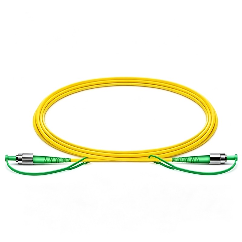
Choose bare fiber, coated fiber, loose tube, or jacketed cable and the required connector. APC connectors reduce back reflection, but mating equipment must be compatible.
7. Check Environmental and Mechanical Requirements
Specify pigtail length, package dimensions, temperature, humidity, vibration, and mounting constraints. Field and industrial systems may require qualification beyond a laboratory component.
Frequently Asked Questions
Is an optical circulator a passive device?
Most fiber optic circulators are passive and require no external electrical power. Their nonreciprocal behavior is produced by magneto-optic materials under a permanent magnetic bias.
Can an optical circulator be connected backward?
It should be connected according to its marked port sequence. Reversing arbitrary input and output ports will normally result in high loss or route the signal to an unexpected port.
Does a three-port circulator always support Port 3 → Port 1?
No. Some ideal diagrams show a complete cyclic path, but many commercial three-port products guarantee only Port 1 → Port 2 and Port 2 → Port 3. Check the manufacturer’s port diagram and specifications.
Can one circulator operate at any wavelength?
No. Faraday rotation, coatings, fiber properties, coupling efficiency, and isolation are wavelength dependent. Use the device only within its specified wavelength range.
What is the difference between a PM and polarization-independent circulator?
A polarization-independent circulator is designed to provide relatively stable performance for changing input polarization. A PM circulator uses polarization-maintaining fiber to preserve a properly aligned polarization state and is intended for polarization-sensitive systems.
Can an optical circulator replace a fiber coupler?
Only in certain system layouts. A coupler splits or combines optical power according to a coupling ratio, while a circulator routes light according to the input port and propagation direction. They are not generally interchangeable.
Conclusion
An optical circulator is a nonreciprocal router that separates signals according to port and propagation direction. It allows a transmitter and receiver to share one fiber, separates sensor returns from a source, routes wavelengths reflected by an FBG, and supports laser, amplifier, sensing, dispersion-compensation, and OCT systems.
The correct device should be selected by considering wavelength and bandwidth, port routing, insertion loss, isolation, directivity, polarization, optical power, fiber type, connector polish, and environmental conditions as a complete set.
Firsol provides standard single-mode, polarization-maintaining, and high-power optical circulators for a range of operating wavelengths and system configurations. Custom fiber, connector, pigtail, package, and optical-performance options are available. When requesting a quotation, provide the required wavelength range, port count, fiber type, CW or pulsed power, connector type, pigtail length, and target insertion-loss and isolation levels so that the appropriate configuration can be evaluated.