What Is Polarization Maintaining Fiber? Working Principle, Types, and Selection
Polarization maintaining fiber (PM fiber or PMF) is an optical fiber designed to preserve the linear polarization of light when the input polarization is aligned with one of its two principal axes. It achieves this through strong built-in birefringence, which helps reduce unwanted power coupling between the two orthogonal polarization modes.
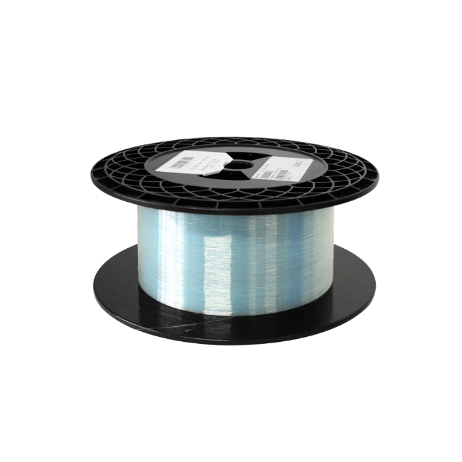
PM fiber is used in fiber lasers, optical sensors, interferometers, and connections between polarization-sensitive components. However, it does not automatically polarize light or preserve every possible input polarization state. Understanding this distinction is essential when selecting PM fiber, assembling a PM patch cable, or troubleshooting a polarization-sensitive optical system.
Why Does Polarization Matter in Optical Fiber?
Polarization describes the behavior of the electric field of a light wave. For linearly polarized light, the electric field oscillates along a fixed direction perpendicular to propagation. Circularly and elliptically polarized light have electric-field directions that rotate as the wave evolves.
A conventional single-mode fiber supports two orthogonal polarization modes within its fundamental spatial mode. “Single-mode” therefore does not mean “single-polarization.” Small asymmetries, residual stress, bending, and temperature changes can alter the relative phase and coupling of these polarization components, changing the output state of polarization.
This matters when a downstream component responds differently to different polarization orientations. A changing input polarization may affect the response of a modulator, the contrast of an interferometer, or the power transmitted through a polarizer.
How Does Polarization Maintaining Fiber Work?
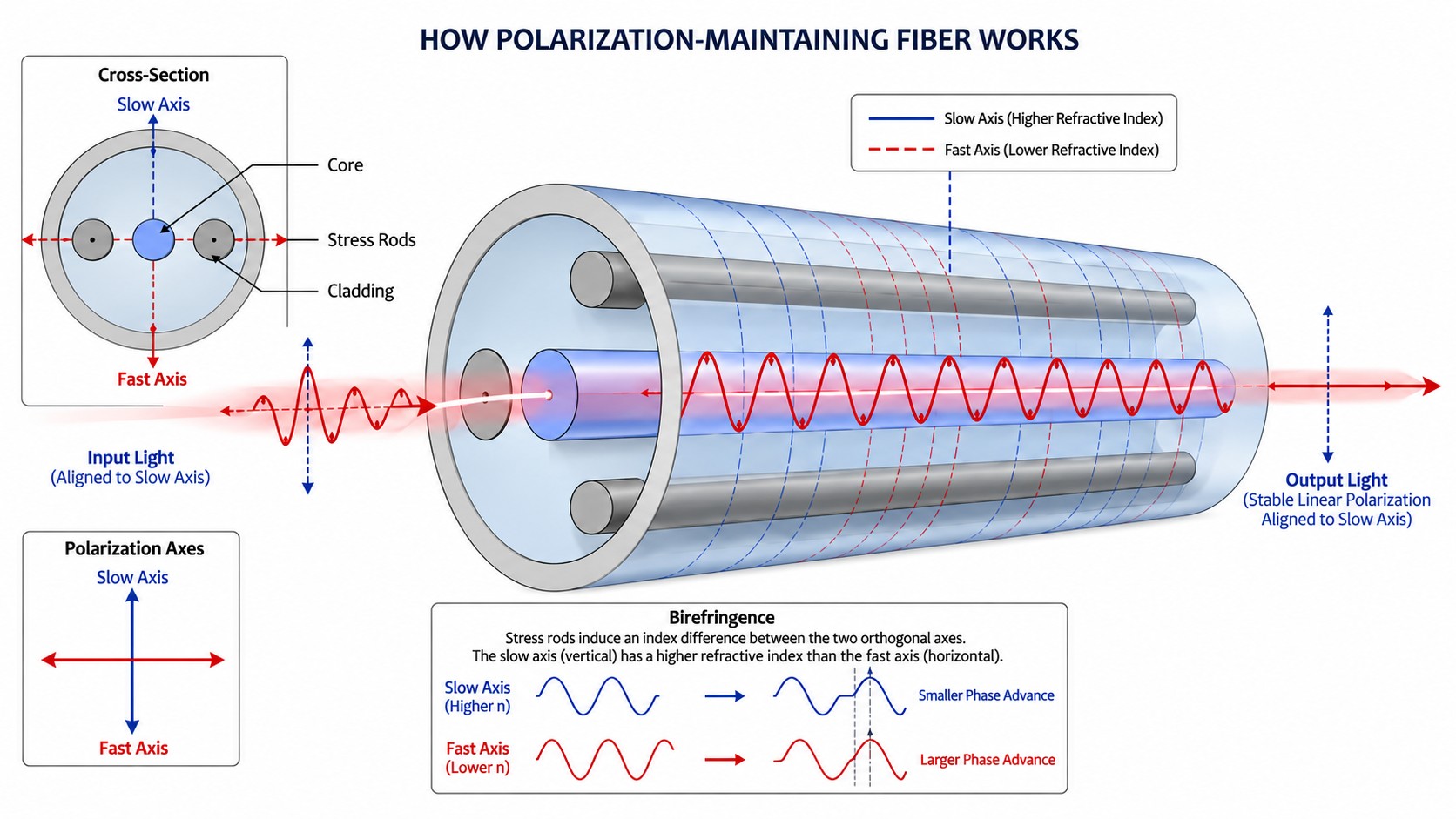
PM fiber deliberately introduces a difference between the effective refractive indices of two orthogonal polarization modes. This difference is called birefringence. The associated principal axes are known as the slow axis and fast axis.
Slow axis: The polarization mode has the higher effective refractive index and lower phase velocity.
Fast axis: The polarization mode has the lower effective refractive index and higher phase velocity.
Strong built-in birefringence separates the propagation constants of these modes and reduces their susceptibility to coupling from many common perturbations. If linearly polarized light is launched along one principal axis, most of the power remains in that polarization mode as it travels through the fiber.
Both axes can support polarization-maintaining transmission. The axis used in a system should match the requirements of the connected components. Many PM cable assemblies align the slow axis with the connector key, but this is an assembly specification rather than a universal rule that makes the fast axis unsuitable for precision work.
PM Fiber Is Not a Polarizer
Ordinary PM fiber supports both orthogonal polarization modes. If the input polarization is misaligned with the principal axes, both modes are excited. Their relative phase changes during propagation, and the output may become elliptically polarized.
PM fiber therefore does not convert arbitrary input light into a single, stable linear polarization. A polarizer selects a polarization component; a PM fiber preserves a suitably launched polarization. These functions are different.
PM Fiber vs. Standard Single-Mode Fiber
Characteristic | Standard Single-Mode Fiber | Polarization Maintaining Fiber |
|---|---|---|
Main design objective | Single-spatial-mode transmission with the required loss and dispersion characteristics | Single-spatial-mode transmission with controlled polarization behavior |
Birefringence | Generally low and affected by imperfections and environmental conditions | Deliberately introduced, relatively strong birefringence |
Output polarization | May change as wavelength, routing, or environmental conditions change | Linear polarization can be maintained when correctly launched along a principal axis |
Assembly requirements | Usually no rotational polarization-axis alignment | Requires axis alignment where polarization continuity is needed |
Typical uses | Telecom links, data transmission, and many sensing systems | Polarization-sensitive component connections, lasers, sensors, and interferometers |
PM fiber is not automatically a better replacement for standard single-mode fiber. It adds alignment requirements and should be selected when polarization control is necessary. Standard single-mode fiber also supports coherent optical communication; the word “coherent” does not imply that the transmission link must use PM fiber.
Common Types of Polarization Maintaining Fiber
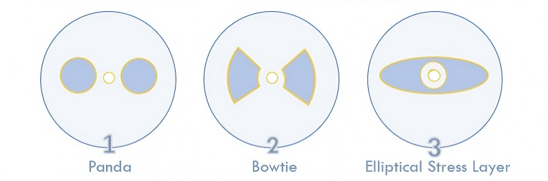
PM fibers generate birefringence through internal stress, asymmetric waveguide geometry, or a combination of these effects. The following structures are common examples rather than an exhaustive classification.
PANDA Fiber
PANDA fiber contains two approximately circular stress-applying regions on opposite sides of the core. Differences in thermal contraction during manufacturing create an asymmetric stress distribution that induces birefringence.
PANDA designs are widely available for component pigtails, patch cables, sensors, and other polarization-sensitive applications. Their visible stress regions also provide orientation references during fiber alignment.
Bow-Tie Fiber
Bow-Tie fiber uses stress-applying regions shaped approximately like opposing wedges. This structure can provide strong stress-induced birefringence.
Commercial Bow-Tie fibers serve a range of applications, including gyroscopes, current sensors, and telecommunications components. They should not be described as suitable only for one class of high-precision interferometer.
Elliptical-Core and Elliptical-Stress Designs
An elliptical core breaks the rotational symmetry of the waveguide and can produce form birefringence. Elliptical-stress designs instead use an asymmetric stress distribution around the core. These mechanisms should not be treated as identical.
The structure alone does not establish a universal performance ranking. Compare actual specifications at the required wavelength, including beat length, attenuation, mode field diameter, and polarization performance under the intended operating conditions.
Key Specifications Explained
Birefringence
The magnitude of phase birefringence can be expressed as:
B = |neff,slow − neff,fast| = |βslow − βfast| / k0
Where:
B is the dimensionless magnitude of phase birefringence.
neff,slow and neff,fast are the effective refractive indices of the two polarization modes.
βslow and βfast are their propagation constants.
k0 = 2π / λ is the free-space wave number.
λ is the wavelength in vacuum.
Beat Length
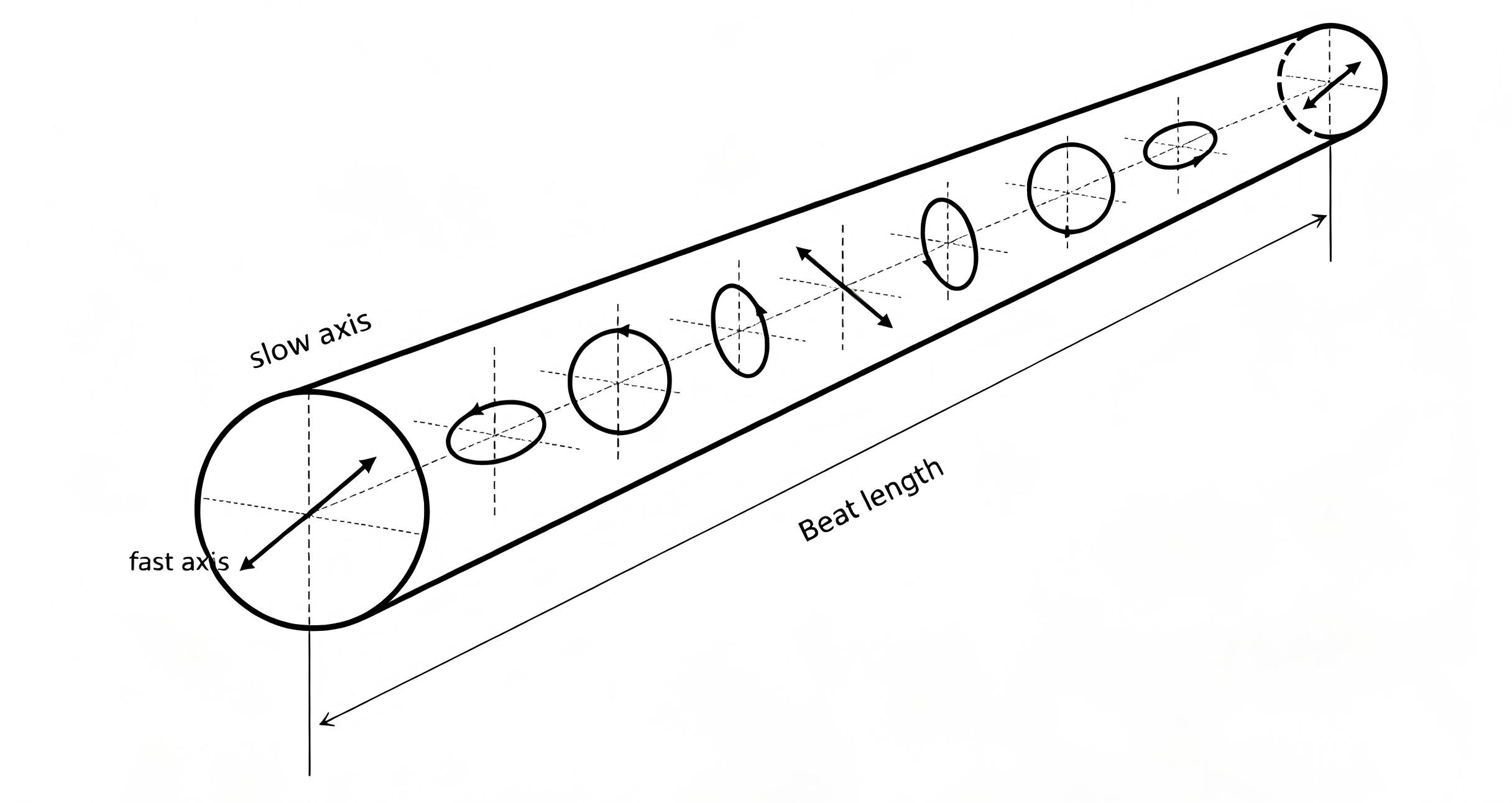
Beat length is the distance over which the two polarization modes accumulate a relative phase difference of 2π:
LB = 2π / |βslow − βfast| = λ / B
At a given wavelength, a shorter beat length indicates stronger birefringence. It does not, by itself, guarantee better performance for a complete cable assembly or system. Beat length must be compared at a stated wavelength, and other requirements still need to be checked.
Polarization Extinction Ratio and Crosstalk
For an axis-referenced measurement, polarization extinction ratio can be expressed as:
PER (dB) = 10 log10(P∥ / P⊥)
P∥ is the output power in the intended polarization component, and P⊥ is the power in the orthogonal component. For example, a power ratio of 1000:1 corresponds to a PER of 30 dB.
Polarization crosstalk is often reported using the inverse ratio:
XT (dB) = 10 log10(P⊥ / P∥)
With these definitions and the same measurement conditions, XT equals −PER. Check the supplier’s convention, since positive isolation values and negative crosstalk values may both appear in specifications.
A PER figure should be read together with the test wavelength, fiber length, input polarization, and assembly conditions. Connector alignment, splices, bending, and mechanical stress can affect the result. Bare-fiber specifications and finished-cable specifications are not necessarily directly comparable.
H-Parameter
The polarization holding parameter, or h-parameter, characterizes polarization coupling per unit length. In a weak-coupling approximation:
h ≈ P⊥ / (P∥ × L)
Here, L is the tested fiber length, and the power ratio is linear rather than expressed in dB. The unit is typically m−1. Lower values indicate less coupling under the stated conditions. Temperature and fiber deployment can influence the measured result.
For short connectorized cables, a specified assembly PER is often more directly useful to a buyer than an h-parameter alone.
How to Choose PM Fiber or a PM Fiber Patch Cable
Begin with the operating wavelength and the components that the fiber will connect. Then confirm the optical and mechanical requirements of the entire connection.
Selection Item | What to Check |
|---|---|
Operating wavelength | The recommended operating range of the actual fiber model |
Cutoff wavelength | Whether single-mode operation is supported at the intended wavelength |
Mode field diameter (MFD) | Compatibility with the connected fiber or optical component |
PER or crosstalk | Required performance and the conditions under which it is specified |
Connector and end face | The correct interface and polish for the mating component |
Axis alignment | Slow-axis or fast-axis alignment and its relationship to the connector key |
Length and protection | Routing length, buffer or jacket, and strain-relief requirements |
Environment | Temperature range, bending limits, and mechanical loading |
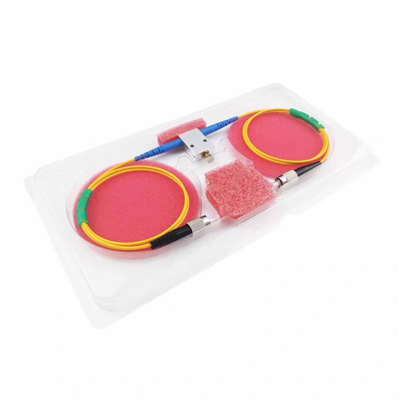
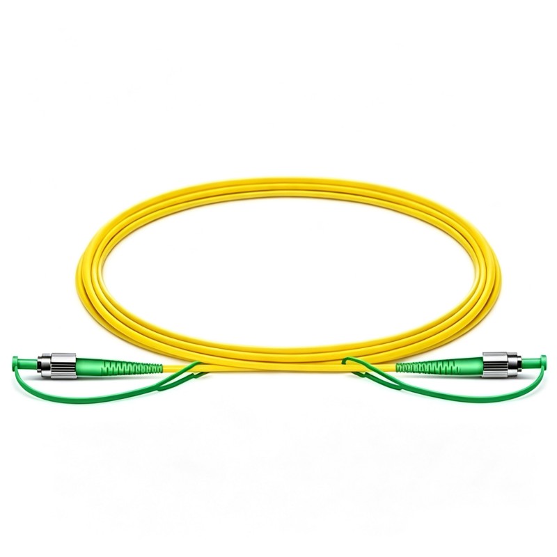
For example, selecting a 1550 nm PM fiber patch cable involves more than matching the wavelength. The fiber type, connectors, axis orientation, cable length, and required PER must also match the system.
When replacing an existing assembly, provide its fiber model and connector specifications where possible. Similar external appearance does not establish optical compatibility.
Installation and Handling
Good fiber specifications alone cannot compensate for poor assembly or handling.
Confirm the axis convention. Check both ends of the connection and the requirements of any polarization-sensitive component.
Use appropriate PM splicing procedures. Core alignment and rotational axis alignment both matter.
Follow bending limits. Avoid tight bends, sharp clamps, and strain concentrated near connector boots or splice protectors.
Inspect and clean connector end faces. Contamination can increase loss and make measurements unreliable.
Verify performance in the intended setup. Where polarization performance is critical, measure after installation under representative conditions.
If the measured PER is lower than expected, check the input polarization and launch alignment before concluding that the fiber is defective. Also examine connectors, splices, routing, and the measurement reference.
Where Is PM Fiber Used?
Fiber Lasers and Amplifiers
PM fiber provides defined polarization paths in systems designed around polarization-sensitive gain, filtering, or output requirements.
Interferometers and Sensors
Controlled polarization can help maintain the required interference response in suitably designed optical sensors and measurement systems.
Polarization-Sensitive Component Connections
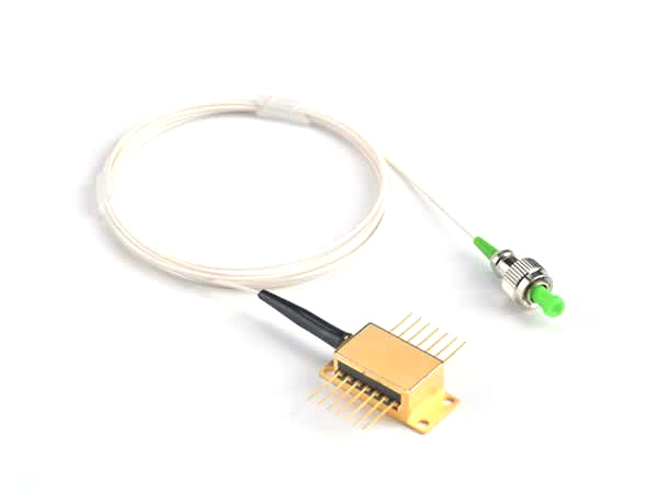
Laser pigtails, external modulators, and other optical components may require a defined input polarization. PM fiber helps maintain that relationship between components.
Quantum Optics and Laboratory Experiments
PM fiber can be useful in paths requiring stable linear polarization. It should not be assumed to preserve an arbitrary polarization state or polarization-encoded signal without considering differential phase and the full system design.
Frequently Asked Questions
Is PM fiber still single-mode fiber?
Many commonly used PM fibers are designed for single-spatial-mode operation over a specified wavelength range. They nevertheless support two orthogonal polarization modes. Always check the operating range of the selected model.
Can PM fiber maintain polarization along the fast axis?
Yes. Conventional PM fiber can maintain appropriately launched linear polarization along either principal axis. A particular connected device may require one axis, so follow its alignment specification.
What happens if the input polarization is not aligned?
Both polarization modes can be excited. Their changing relative phase can produce an output polarization different from the input, even when coupling between the modes is small.
Does a shorter beat length always mean a better fiber?
No. At the same wavelength, it indicates stronger birefringence. Overall suitability also depends on loss, wavelength range, MFD, assembly quality, and performance in the intended environment.
Can PM fiber be connected to ordinary single-mode fiber?
Yes, provided the optical and mechanical interfaces are compatible. However, a standard non-PM section does not provide the same polarization-maintaining behavior, so the complete path should not be assumed to retain PM performance.
What information should I provide when ordering a PM patch cable?
Specify the wavelength, fiber model if known, cable length, connectors, end-face polish, required axis alignment, and PER requirement. Include any temperature, bending, or packaging constraints.
Discuss Your PM Fiber Requirements with FIRSOL
When specifying a PM fiber assembly, start with the optical interfaces and polarization requirements of your system. Contact [email protected] with your operating wavelength, fiber type, connector requirements, length, and target PER to discuss suitable options.