What Is an In-line Polarizer? How It Works, Specs & Applications
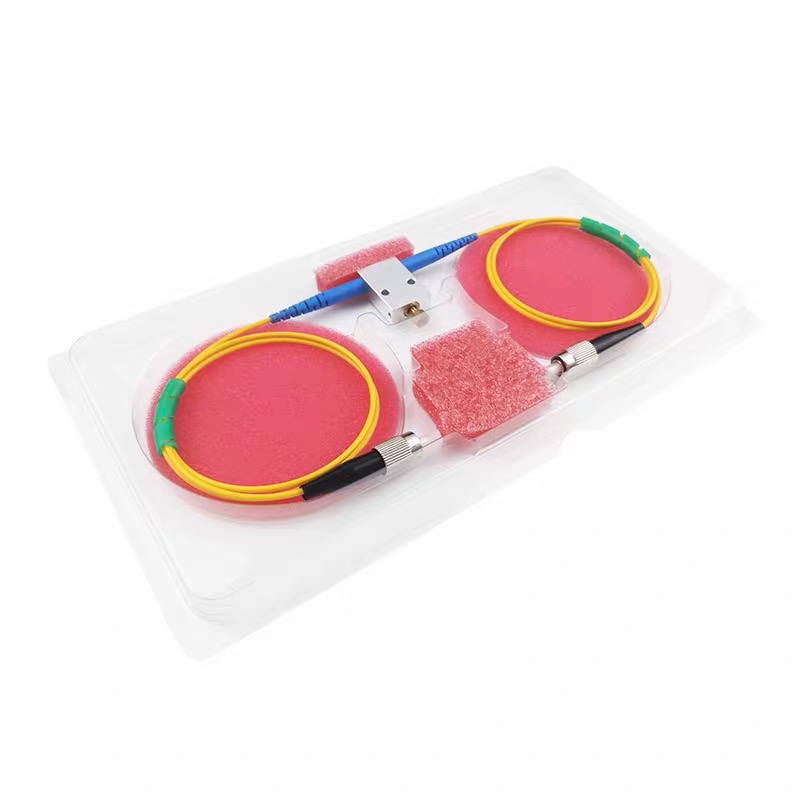
An in-line polarizer is a fiber-pigtailed optical component that transmits light polarized along one axis while strongly attenuating the orthogonal polarization. In fiber optic systems it is used to clean up the polarization state of a signal, define a stable linear polarization reference, and suppress unwanted polarization components before sensitive downstream devices such as modulators, interferometers, and coherent receivers.
Unlike a free-space polarizing plate used in cameras or sunglasses, an in-line polarizer is fully fiber-coupled, typically built with polarization maintaining (PM) fiber pigtails so the output polarization stays aligned to a known axis. This makes it a core building block in fiber lasers, fiber optic sensing, coherent communication, and optical test instrumentation.
How an In-line Polarizer Works
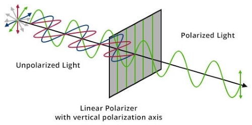
Light is an electromagnetic wave whose electric field can oscillate in any plane perpendicular to its direction of travel. In an ordinary fiber, the polarization state drifts randomly with temperature, stress, and bending. An in-line polarizer enforces order: it passes the field component aligned to its transmission axis and blocks the perpendicular component, producing a clean, linearly polarized output.
The performance of this filtering is measured by the extinction ratio (ER) — the power ratio between the transmitted (pass) axis and the blocked (reject) axis. A higher extinction ratio means a purer polarization state. In PM-pigtailed designs, the transmission axis is aligned to the slow axis of the PM fiber by default, so the output polarization is both well-defined and stable as it propagates.
Construction and Materials
In-line polarizers rely on materials and structures that are intrinsically polarization-selective. Common approaches include dichroic polarizing elements, birefringent crystals such as calcite, and thin-film or wire-grid polarizing structures, all coupled to fiber pigtails inside a compact metal package. PM fiber (such as PANDA-type PM1550) is used for the pigtails so the cleaned polarization is maintained along a fixed axis after the device.
Key Specifications to Consider
When selecting an in-line polarizer for an optical communication or sensing system, the product name alone is not enough. Review the parameters below before ordering.
Parameter | Typical Value | Why It Matters |
|---|---|---|
Extinction Ratio (ER) | ≥22dB (up to 30dB+) | Defines polarization purity of the output |
Insertion Loss (IL) | ≤0.6dB (typ.) | Power lost through the device; lower is better |
Operating Wavelength | 1310nm / 1550nm (or custom) | Must match your system band |
Bandwidth | ±15nm typical | Wavelength window over which ER/IL are guaranteed |
Return Loss (RL) | ≥50dB | Suppresses back reflections into the source |
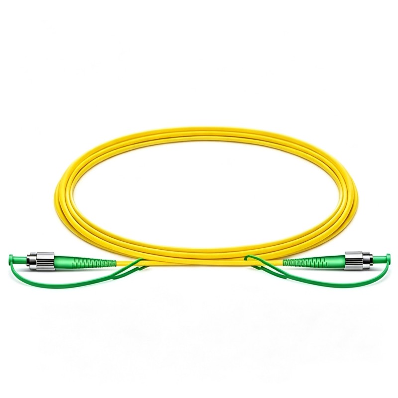
Fiber Type | PM1550 / SMF-28e | PM preserves the output polarization axis |
Optical Power Handling | 0.3W – 5W | Match to laser / amplifier power level |
Operating Temperature | -5°C to +70°C | Stability across the deployment environment |
For most fiber laser and coherent systems, a high extinction ratio (≥22dB) combined with low insertion loss is the priority. Adding connectors will typically increase IL by ~0.3dB and may slightly reduce extinction ratio, so specify pigtail vs. connectorized at the quoting stage.
In-line Polarizer vs PM Fiber Alone
A common question is whether PM fiber by itself is enough. PM fiber maintains a polarization state once it is launched correctly, but it does not create a clean one. An in-line polarizer actively removes the unwanted orthogonal component, which is why the two are often used together: the polarizer defines the state, and the PM pigtail preserves it downstream.
Typical Applications
In-line polarizers are used wherever a stable, high-purity linear polarization state is required in a fiber path. Common applications include:
Coherent optical communication — clean polarization reference before modulators and coherent receivers.
Fiber lasers and amplifiers — enforcing a defined polarization state for stable output.
Fiber optic sensing — interferometric and gyroscope sensors that depend on polarization stability.
Optical test and measurement — providing a known polarization input for instrumentation and lab setups.
Polarization-sensitive research — microscopy, spectroscopy, and quantum optics experiments.
Frequently Asked Questions
Q1: What is the difference between an in-line polarizer and a polarizing beam splitter?
An in-line polarizer transmits one polarization and absorbs or rejects the other, giving a single clean output. A polarizing beam splitter separates the two polarization components into two output ports. Use a polarizer when you only need one defined state and want to discard the rest.
Q2: Do I need PM fiber pigtails?
For most applications, yes. PM pigtails keep the cleaned polarization aligned to a fixed axis after the device. If the output goes immediately into a non-polarization-critical path, a single-mode pigtail may be acceptable, but PM is the standard for fiber lasers, coherent systems, and sensing.
Q3: What extinction ratio do I need?
It depends on the system. General fiber laser and instrumentation use is often satisfied with ≥22dB, while high-precision coherent or interferometric systems may require 25–30dB or higher. Specify your target ER when requesting a quote.
Q4: How much insertion loss does an in-line polarizer add?
Typical insertion loss is around 0.6dB or less for a pigtailed device. Adding connectors usually increases IL by approximately 0.3dB per connector, so account for this in your power budget.
Q5: Can an in-line polarizer handle high optical power?
Yes, within its rated limit. Standard devices handle power levels in the 0.3W–5W range. For high-power fiber laser or amplifier systems, confirm the power rating when ordering.
Conclusion
An in-line polarizer is a compact, fiber-coupled component that delivers a clean, stable, high-purity linear polarization state inside an optical system. By combining a high extinction ratio with low insertion loss and PM fiber pigtails, it ensures that polarization-sensitive devices — from coherent receivers to fiber lasers and interferometric sensors — receive a well-defined polarization reference.
Firsol supplies in-line polarizers with custom operating wavelengths, extinction ratios, fiber types, optical power levels, pigtail lengths, and connector options to match a wide range of optical communication and sensing requirements.