What Is Single-Mode Fiber?
Single-mode fiber (SMF) is an optical fiber designed to guide only the fundamental mode of light at its operating wavelengths. It typically has a core diameter of approximately 8 to 10 µm and a standard cladding diameter of 125 µm. Because it does not suffer from modal dispersion, single-mode fiber can support high-capacity transmission over substantially longer distances than multimode fiber.
Single-mode fiber is widely used in telecommunications, fiber-to-the-home (FTTH), data center interconnects, metropolitan networks, enterprise backbones, cable television systems, and other applications that require low loss and high bandwidth over distance.
What Is Single-Mode Fiber?
Single-mode fiber is a glass optical waveguide with a core that is small enough to suppress higher-order modes above its cutoff wavelength. In practical communications systems, most of the optical power propagates in the fundamental LP01 mode. This is more precise than saying that a single “ray” or “light path” travels through the fiber, because the optical field occupies both the core and a small portion of the cladding.
Standards commonly specify the mode field diameter (MFD), rather than only the physical core diameter. For ITU-T G.652.D fiber, the nominal MFD at 1310 nm is generally within the range specified by the applicable standard, while the cladding diameter is 125 µm.
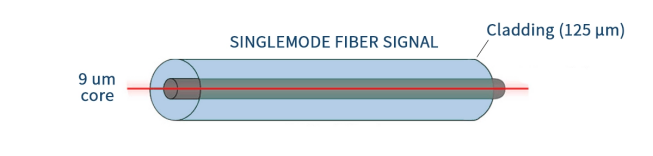
Figure 1. Simplified single-mode fiber illustration (not to scale).
How Does Single-Mode Fiber Work?
The refractive index of the core is slightly higher than that of the surrounding cladding. This refractive-index profile confines the optical field and allows the fiber to operate as a waveguide. When the fiber is used above its cutoff wavelength, higher-order modes are not supported and the fundamental mode carries the signal.
Eliminating higher-order modes removes modal dispersion, which is the pulse spreading caused by different modes arriving at different times. Single-mode systems are still affected by attenuation, chromatic dispersion, polarization-mode dispersion, connector loss, splice loss, and reflections, so the total system reach must be determined from the complete optical link design.
Main Parts of a Single-Mode Fiber Cable
A bare optical fiber and a finished fiber cable are not the same structure. The glass fiber contains the core and cladding, followed by protective coating. A cable adds mechanical and environmental protection around the coated fiber.
Core: The central glass region that guides most of the optical power.
Cladding: A 125 µm glass layer with a slightly lower refractive index that helps confine the optical field.
Primary Coating: A protective polymer layer applied to the glass fiber to reduce damage from moisture, abrasion, and microbending.
Buffer or Tube: A tight buffer or loose tube that provides additional mechanical protection, depending on the cable design.
Strength Members: Aramid yarn, fiberglass-reinforced plastic, or other elements that carry tensile loads.
Outer Jacket: The external protective layer selected for the installation environment, flame rating, and mechanical requirements.
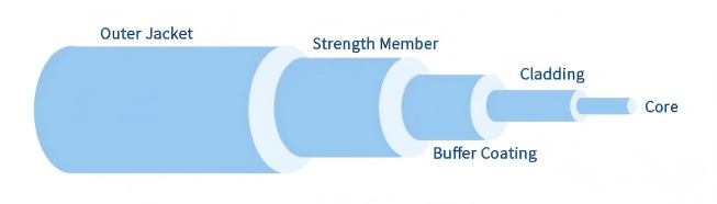
Figure 2. Simplified optical cable construction. Actual cable designs vary by application.
Common Single-Mode Fiber Types
Single-mode fiber products are identified by several different classification systems. ITU-T designations describe fiber transmission and mechanical characteristics, while OS1 and OS2 describe cabled optical fiber categories used in structured cabling. These terms should not be treated as interchangeable.
ITU-T G.652.D
G.652.D is a widely deployed low-water-peak single-mode fiber for general transport, access, enterprise, and data center networks. Its zero-dispersion wavelength is around 1310 nm, and it can also be used in the 1550 nm region. It supports transmission across a broad wavelength range and is commonly used in OS2 cables and patch cords.
ITU-T G.657 Bend-Insensitive Fiber
G.657 fiber is designed to reduce macrobending loss where cables must be routed through compact spaces or around tighter bends. Common categories include:
· G.657.A1: Bend-insensitive fiber designed for a minimum design radius of 10 mm and compliant with G.652.D transmission requirements.
· G.657.A2: Enhanced bend performance with a minimum design radius of 7.5 mm and compatibility with G.652.D applications.
· G.657.B3: Very low bending loss at a minimum design radius of 5 mm, intended mainly for short-reach access, in-building, and compact interconnection applications. It is not necessarily fully compliant with every G.652.D transmission parameter.
OS1 vs. OS2 Single-Mode Cable
OS1 and OS2 are performance categories for cabled single-mode optical fiber. They do not define whether a cable must be tight-buffered or loose-tube. Both constructions can be manufactured as OS2, so the cable structure should be selected according to the installation environment rather than inferred from the OS category.
Feature | OS1 | OS2 |
Typical maximum cabled attenuation | 1.0 dB/km at 1310 nm and 1550 nm | 0.4 dB/km at 1310 nm and 1550 nm |
Water-peak requirement | Depends on the applicable specification and product | Low-water-peak performance is required |
Typical deployment | Legacy or general premises cabling | New premises, campus, outside-plant, access, and longer-reach links |
Cable construction | May use different constructions | May be tight-buffered, loose-tube, ribbon, microcable, or another construction |
Maximum transmission distance | Not fixed by the OS1 designation | Not fixed by the OS2 designation |
For most new single-mode installations, OS2 is the more common choice because of its lower specified attenuation and broader wavelength performance. However, the final selection must also account for flame rating, indoor/outdoor use, tensile load, bend radius, fiber count, connector type, and environmental conditions.
Common Operating Wavelengths
Single-mode communication systems use several wavelength regions. The most common are 1310 nm and 1550 nm:
· 1310 nm: G.652 fiber has a zero-dispersion wavelength around 1310 nm. This region is commonly used for access, enterprise, and shorter-to-medium-reach single-mode links.
· 1550 nm: Standard single-mode fiber generally has lower attenuation in the 1550 nm region, making it valuable for longer links. Chromatic dispersion is higher than near 1310 nm and must be considered in high-speed or long-distance systems.
· Other wavelengths: 1490 nm, 1577 nm, 1625 nm, and additional wavelengths may be used in PON, WDM, monitoring, and specialized systems. Compatibility must be confirmed for the transceivers, passive components, and fiber type.
Advantages of Single-Mode Fiber
Long transmission reach: Low attenuation and the absence of modal dispersion make SMF suitable for links ranging from local access networks to long-haul transmission systems.
High bandwidth-distance capability: Single-mode fiber supports high data rates over long distances when used with appropriate optical transceivers and system designs.
Scalable infrastructure: Many capacity upgrades can be implemented by changing optical equipment or adding wavelengths without replacing an installed fiber plant that remains within specification.
Support for WDM: Low-water-peak fibers can support wavelength-division multiplexing across multiple optical bands, subject to component and system compatibility.
Immunity to electromagnetic interference: Like other optical fibers, SMF is nonconductive and unaffected by radio-frequency or electromagnetic interference.
Small size and high fiber density: Single-mode fibers can be incorporated into high-count cables for space-efficient network deployment.
Single-Mode Fiber vs. Multimode Fiber
Feature | Single-Mode Fiber (SMF) | Multimode Fiber (MMF) |
Typical core size | Approximately 8 to 10 µm | 50 µm or 62.5 µm |
Supported modes | Fundamental mode | Multiple modes |
Common light source | Laser-based transmitter | VCSEL or LED, depending on the application |
Primary dispersion concern | Chromatic dispersion and PMD at high speed/distance | Modal dispersion, plus chromatic dispersion |
Typical reach | From short links to tens or hundreds of kilometers, depending on the optical interface and link design | Primarily short-reach links; exact distance depends on OM category, data rate, and optical standard |
Optical component cost | Can be higher for some short-reach applications | Often economical for short data center or building links |
Typical applications | Telecom, FTTH, DCI, metro, campus backbones, CATV, long-reach enterprise networks | Equipment rooms, data halls, building LANs, and other short-reach interconnects |
Neither fiber type is universally better. Single-mode fiber is normally preferred when reach, upgrade flexibility, or wavelength multiplexing is the priority. Multimode fiber can remain cost-effective for short links when the installed cabling and optical interface are matched correctly.
Where Is Single-Mode Fiber Used?
Telecommunications and internet backbones: Long-haul, metro, and core networks require high capacity and low transmission loss.
FTTH and broadband access: Passive optical networks use single-mode fiber between the service provider and homes or buildings.
Data center interconnect: SMF connects separate data centers and can also be used inside data centers where longer reach or future scalability is required.
Enterprise and campus backbones: Links between buildings often exceed the practical reach of multimode systems.
5G transport networks: Fronthaul, midhaul, and backhaul networks use single-mode fiber to connect radio, aggregation, and core equipment.
CATV and video distribution: Optical links transport broadcast and broadband signals over regional distribution networks.
Industrial and utility networks: SMF supports long cable runs and electrically isolated communications in harsh or high-interference environments.
Laboratories and sensing systems: Specialized single-mode fibers are used in interferometry, sensing, lasers, test systems, and research applications.
How to Maintain Single-Mode Fiber Performance
1. Select compatible components. Confirm that the fiber, transceivers, splitters, WDM devices, connectors, adapters, and test equipment are intended for the same wavelength range and fiber type.
2. Calculate the optical link budget. Include fiber attenuation, connector loss, splice loss, splitter or filter loss, engineering margin, transmitter output, and receiver sensitivity.
3. Control connector cleanliness. Inspect and clean connector end faces before mating. Contamination is a common cause of insertion loss, reflection, and equipment damage.
4. Match connector polish. UPC and APC interfaces should not be directly mated. Use compatible connector types, adapters, and end-face polish throughout the connection.
5. Respect bend-radius and pulling limits. Follow the cable manufacturer’s installation and operating specifications rather than applying a universal bend radius to every cable.
6. Test the installed link. Use an optical loss test set for end-to-end insertion loss and an OTDR when event location, splice evaluation, or fault analysis is required.
Frequently Asked Questions
Is 9/125 fiber the same as OS2?
No. “9/125” describes the approximate core and cladding geometry, while OS2 is a cabled-fiber performance category. A 9/125 product may be OS1, OS2, or described under another applicable specification.
Can OS2 cable be tight-buffered?
Yes. OS2 specifies optical performance, not a mandatory cable construction. Commercial OS2 products are available in tight-buffered, loose-tube, ribbon, and other cable designs.
How far can single-mode fiber transmit?
There is no single maximum distance. The reach depends on the optical standard, transceiver output and sensitivity, wavelength, attenuation, chromatic dispersion, splices, connectors, passive devices, and system margin. Common interfaces range from a few hundred meters to 2 km, 10 km, 40 km, 80 km, or farther.
Can G.657 fiber be connected to G.652.D fiber?
G.657.A1 and G.657.A2 are designed to be compatible with G.652.D transmission characteristics. G.657.B fibers are system-compatible for intended access applications but are not necessarily compliant with every G.652.D parameter. Verify the product specification for critical links.
Can single-mode and multimode fiber be connected together?
A physical connection may be possible with compatible connector hardware, but the optical mismatch causes significant performance problems and is not a valid substitute for a properly designed link. The fiber type must match the optical interface.
Conclusion
Single-mode fiber is the primary transmission medium for networks that require high capacity, long reach, and upgrade flexibility. Its small core supports fundamental-mode propagation and eliminates modal dispersion, but successful deployment still depends on the correct fiber category, cable construction, optical interface, link budget, connector handling, and testing method.
For new projects, OS2 cable containing G.652.D or compatible G.657.A fiber is widely used, while G.657 variants provide additional bending performance for dense access and in-building installations. The best option should be selected from the actual application requirements rather than from a fixed distance or speed assigned to the fiber label.