Fiber Collimator Selection Guide: From C-Lens Physics to Real-World Applications
Why Fiber Collimator Performance Directly Affects Your Optical System
In systems such as LiDAR, fiber amplifiers, and free-space optical links, the output of an optical fiber is inherently divergent. Without proper collimation, this leads to:
Coupling loss
Beam distortion
Back reflection instability
A fiber collimator converts this divergent light into a near-parallel beam, or couples free-space light back into fiber with high efficiency.
In industrial designs, C-Lens fiber collimators are preferred over GRIN-based solutions.
Unlike GRIN lenses, C-Lens (cylindrical lens) structures provide longer working distance and higher thermal stability, making them more reliable in high-power systems and applications requiring WD ≥ 50 mm.
This is why most compact, high-reliability collimators today are based on C-Lens architecture.
SM vs MM vs PM: Where Each Type Actually Fits
Choosing the wrong type is one of the most common causes of system inefficiency.
Single Mode (SM) Fiber Collimator
Use when beam quality and coupling precision are critical.
Typical specs:
Insertion Loss: as low as 0.4–0.5 dB @ 1310/1550 nm
Return Loss: ≥ 50 dB
Beam diameter: ≤ 0.6 mm
Power handling: up to 10 W
Typical fiber:
SMF-28e (1310/1550 nm)
Hi1060 (1064 nm)
Applications:
Optical communication
Precision sensing
Coherent systems
👉 If your system involves tight coupling or long-distance transmission, SM is the default.
Multimode (MM) Fiber Collimator
Use when power handling and alignment tolerance matter more than beam quality.
Typical specs:
Insertion Loss: ≤ 0.4 dB
Wavelength: typically 850 nm and 1310 nm bands
Fiber types: OM1 / OM2 / OM3 / OM4
Power handling: up to 10 W
Applications:
High-power laser systems
Industrial sensing
Illumination systems
👉 MM is more tolerant but cannot achieve SM-level beam quality.
Polarization Maintaining (PM) Fiber Collimator
Use when polarization state must be preserved.
Typical specs:
Extinction Ratio: ≥ 20 dB
Axis alignment: Slow Axis aligned to key (default)
Insertion loss: similar to SM
Power handling: up to 10 W
Applications:
Fiber lasers
Interferometers
Coherent detection
👉 Using non-PM collimators in polarization-sensitive systems will lead to unstable results.
The Four Parameters That Actually Matter
Forget “high performance” marketing terms—these parameters determine real system behavior.
1. Working Distance (WD)
Typical options:
5 mm → compact integration
50 mm → general systems
100 mm → long-distance optical paths
👉 Longer WD increases alignment sensitivity.
2. Wavelength Range
From Firsol specifications:
Visible: 532 nm, 630/670 nm
Near-IR: 780–1550 nm
Mid-IR: up to 2050 nm
👉 Always match:
SMF-28e → telecom band
Hi1060 → 1064 nm
PM fibers → wavelength-specific
3. Beam Diameter
Typical value:
≤ 0.6 mm
Impact:
Smaller beam → higher precision requirement
Larger beam → easier alignment
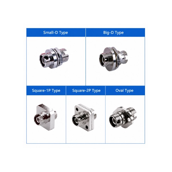
4. Package Type (Often Undervalued)
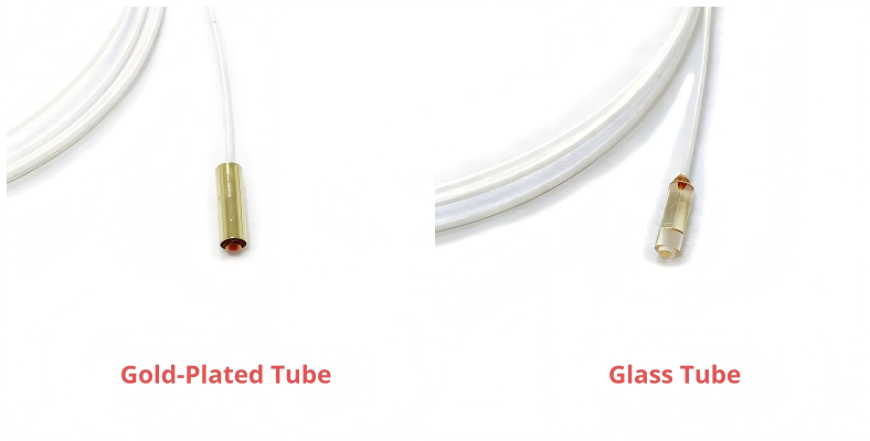
Package Type | Specification | Key Advantage | Recommended Use |
|---|---|---|---|
Glass Tube | Φ2.8 × L9 mm | Compact, cost-effective | Lab setups, non-hermetic systems |
Gold-Plated Tube | Φ3.2 × L10 mm | High mechanical strength, weldable | Industrial modules, LiDAR systems |
👉 If your system involves mechanical integration or vibration, gold-plated housing is the safer choice.
Real Engineering Notes (Not Marketing Claims)
Connector Impact
Adding connectors will:
Reduce Return Loss by ~5 dB
Introduce wavelength-dependent insertion loss
This is explicitly stated in the specifications
👉 Always test performance with the final connector configuration.
Power Handling Is Context-Dependent
Typical range:
0.1 W to 10 W (CW)
In practice, this depends on:
Fiber type
Thermal conditions
Packaging
👉 High-power systems should always include safety margin.
Alignment Is Often the Real Limitation
Especially when:
WD ≥ 50 mm
Beam ≤ 0.6 mm
👉 Mechanical tolerance often dominates system performance, not optical specs.
Typical Applications
Fiber collimators are used where fiber interfaces with free-space optics:
LiDAR systems (compact and stable)
Fiber lasers and amplifiers
Optical communication modules
Laboratory optical systems
FAQ (For Engineers and SEO)
Does adding a connector affect performance?
Yes.
Return loss decreases by ~5 dB
Insertion loss may vary with wavelength
What optical power can a fiber collimator handle?
Typical range:
0.1 W to 10 W (CW)
Actual limit depends on system conditions.
Why is my coupling efficiency low?
Common causes:
Incorrect working distance
Misalignment
Fiber mismatch (SM vs MM)
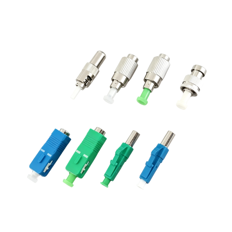
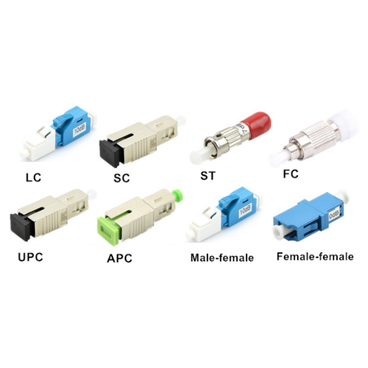
Should I choose FC/APC or FC/UPC?
FC/APC → better return loss (recommended for high-power or sensitive systems)
FC/UPC → general applications
Quick Selection Checklist (Highly Recommended)
Before selecting a fiber collimator, confirm:
Wavelength
Visible (e.g., 630 nm) or telecom (1550 nm)?
Working Distance (WD)
5 mm, 50 mm, or 100 mm?
Fiber Type
SM, MM, or PM?
Pigtail Diameter
250 μm bare fiber or 900 μm loose tube?
Connector Type
FC/APC for best return loss?
Conclusion: Selection Is About Matching, Not Maximizing Specs
Choosing a fiber collimator is not about selecting the “best” specification, but about matching the application requirements:
Telecom / sensing → SM
High power → MM
Polarization-sensitive → PM
A well-matched collimator improves:
Coupling efficiency
System stability
Long-term reliability
Need Technical Support?
If you are working on LiDAR, fiber lasers, or optical communication systems, feel free to contact:
We can assist with configuration selection or custom design.