Fixed Fiber Optic Attenuator: A Complete Guide for Beginners
When Is Less Optical Power Actually Better?
As someone new to fiber optic networks, I used to assume that stronger optical power is always better — after all, we even deploy optical amplifiers to boost weak signals. So why would anyone deliberately reduce optical power?
The answer lies in the receiver, not the transmitter. Single-mode fiber systems typically use laser sources that can output far more power than a receiver is designed to handle. In short-distance links (data centers, equipment rooms, labs), the optical signal arriving at the receiver can exceed its maximum input level, pushing the detector into saturation. The result is pulse distortion, eye diagram closure, and eventually a high bit error rate (BER) — the link may fail even though the signal looks "strong."
The solution: insert a fiber optic attenuator at the receiving end to bring the optical power down to an appropriate level.
What Is a Fixed Fiber Optic Attenuator?
A fixed fiber optic attenuator (also called a fixed plug-type or fixed build-out attenuator) is a passive component that reduces optical power by a predetermined, non-adjustable amount. Typical attenuation values range from 1 dB to 25 dB, and standard tolerance is ±0.5 dB (±10% for values above 10 dB).
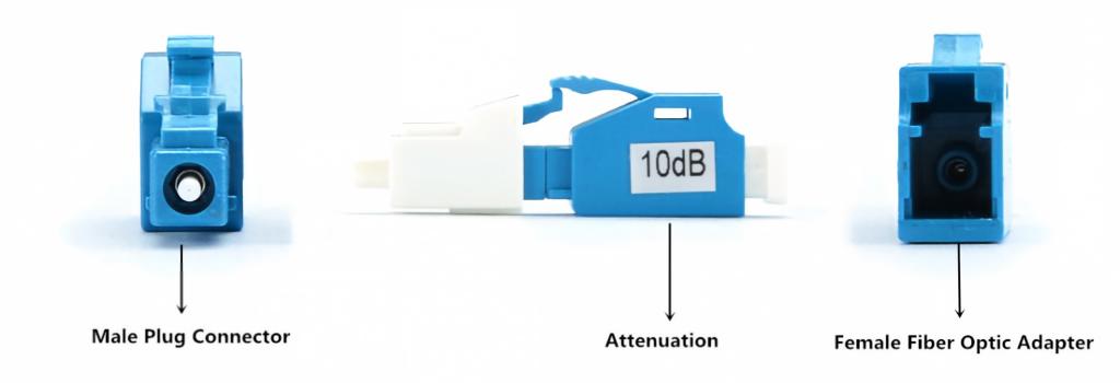
Standard construction features:
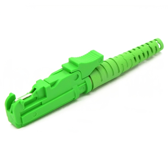
One male plug connector to plug directly into the receiver port or an adapter on a patch panel
One female adapter on the opposite side to accept a patch cord
Naming convention: LC attenuator 10dB = LC connector, 10 dB of attenuation.
Types of Fixed Fiber Optic Attenuators
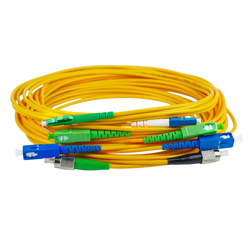
Fixed attenuators are available in LC, SC, ST, FC, MU and MPO connector styles, with UPC or APC polish options.
Connector | Polish | Typical Use |
LC | UPC/APC | SFP/SFP+ transceivers, high-density panels |
SC | UPC/APC | Transceivers, older equipment |
ST/FC | UPC/APC | Legacy networks, test environments |
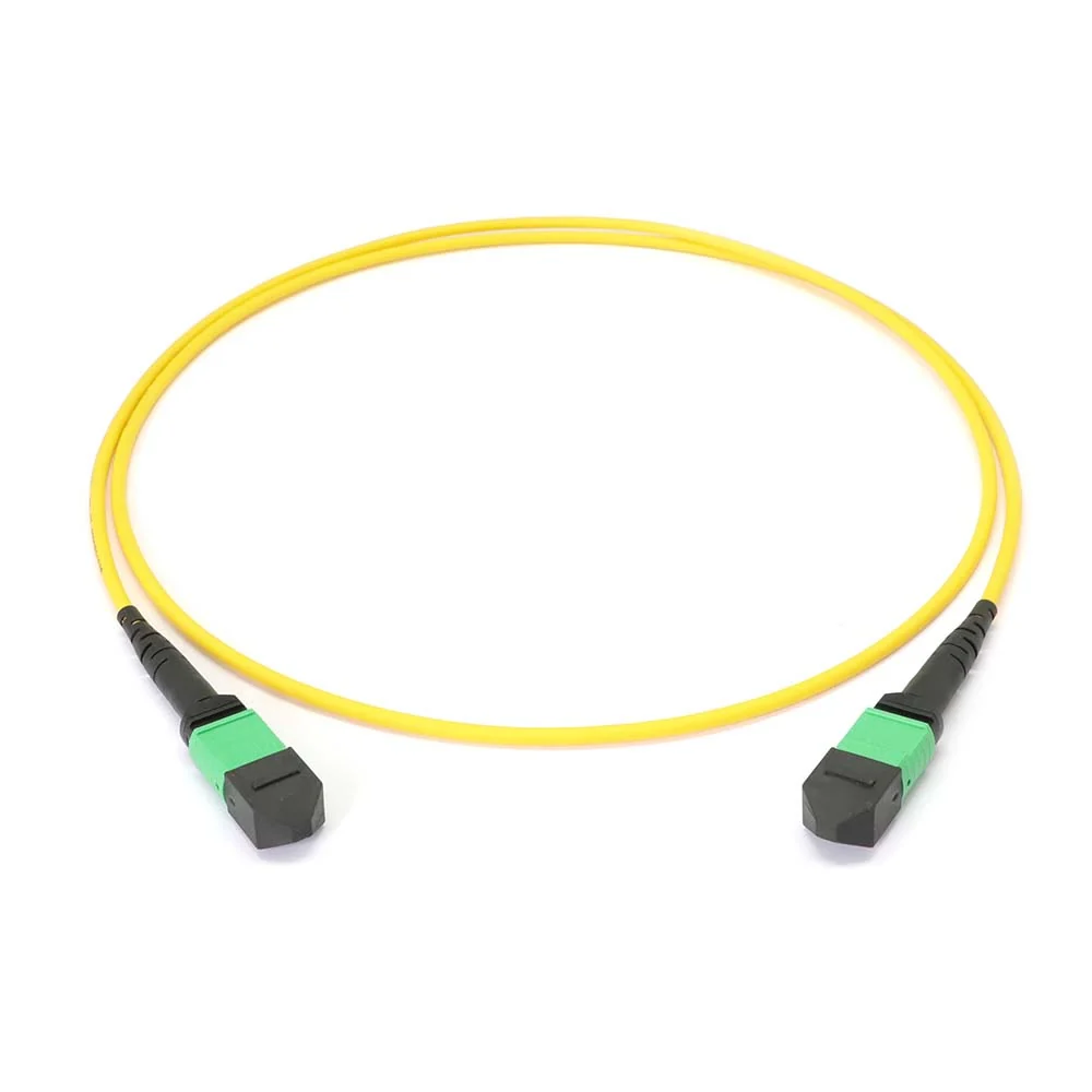
MPO | UPC/APC | Multi-Fiber Communication Systems |
One important note on fiber type: multimode systems rarely need attenuators. Multimode sources (typically VCSELs) rarely output enough power to saturate a receiver. Attenuation challenges are almost exclusively a single-mode, short-link problem — which is why fixed attenuators are almost always single-mode devices.
Two physical configurations exist:
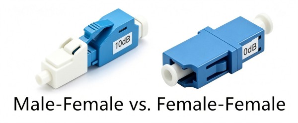
Female-to-male — the most common type; plugs directly into equipment
Female-to-female — female adapters on both ends, functioning as both an attenuator and an in-line adapter, ideal for connecting two patch cords while adding attenuation
How to Use a Fixed Fiber Optic Attenuator
A fixed attenuator should always be installed at the receiving end of the link (position X in the diagram below).
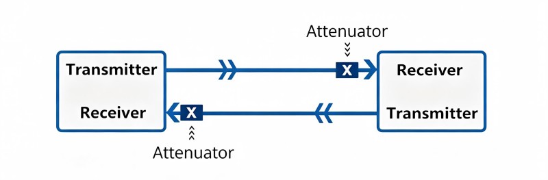
Why the receiving end?
You can conveniently verify power levels before and after attenuation using a power meter at the receiver
Any back-reflection (return loss) introduced by the connection is attenuated on its path back toward the source, minimizing its impact on the transmitter
Installation:
Female-to-male type: plug the patch cord into the female adapter of the attenuator, then insert the male connector directly into the receiver or equipment port.
Female-to-female type: connect the two patch cords from the link into the female adapters on both ends of the attenuator.
Firsol Fixed Fiber Optic Attenuators
Firsol offers a full range of single-mode fixed plug-type attenuators with attenuation values from 1 dB to 25 dB in 1 dB increments, engineered with high return loss and stable performance across both the 1310 nm and 1550 nm wavelength windows. LC and SC types are available in UPC and APC polish; FC, ST, MU and MPO Fiber Optic Attenuators are also offered — all tested to ensure accurate, repeatable attenuation.