Polarization Maintaining Optical Circulators: Working Principle, Specifications & Selection Guide
A Polarization Maintaining Optical Circulator (PM Optical Circulator) is a passive, nonreciprocal fiber optic device designed to direct optical signals between designated ports while preserving the linear polarization of properly aligned light. It combines directional optical routing with polarization-maintaining performance, making it useful in fiber lasers, interferometers, coherent optical systems, and precision fiber optic sensing.
Unlike a conventional polarization insensitive optical circulator, which is designed to operate with varying input polarization states, a PM optical circulator is intended for systems where the polarization orientation must remain controlled.
However, selecting the right PM optical circulator involves more than choosing an operating wavelength. Engineers must also consider the working axis, polarization extinction ratio, insertion loss, isolation, PM fiber compatibility, optical power, and connector alignment.
This guide explains how polarization maintaining optical circulators work, how they differ from polarization insensitive models, and how to select the appropriate configuration for a polarization-sensitive optical system.
1. What Is a Polarization Maintaining Optical Circulator?
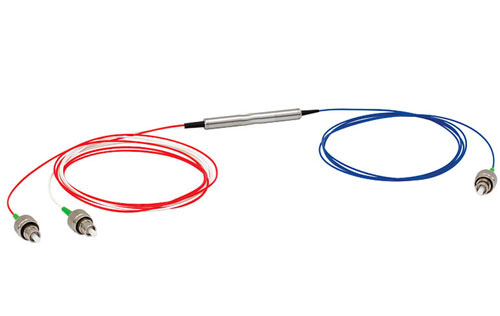
A polarization maintaining optical circulator is a nonreciprocal optical component that combines the directional routing function of an optical circulator with the polarization-preserving characteristics required in PM fiber systems.
Most commonly, it uses a three-port configuration with two specified low-loss transmission paths:
Port 1 → Port 2: Light entering Port 1 is transmitted to Port 2.
Port 2 → Port 3: Light entering Port 2 is directed to Port 3.
Transmission along undesired paths, such as Port 2 → Port 1, is strongly attenuated according to the device's isolation specification.
The nonreciprocal design makes it possible to separate forward-propagating light from reflected or backward-propagating light without using an optical power splitter.
What distinguishes a PM optical circulator is its polarization performance.
The component uses polarization-maintaining fiber and an internal optical arrangement designed to preserve a specified linear polarization orientation. When the input polarization is properly aligned with the supported working axis, the device can maintain a high polarization extinction ratio through the designated optical path.
This capability is particularly important in systems where polarization changes can affect interference contrast, coherent signal detection, measurement repeatability, or other polarization-sensitive performance parameters.
Important: A PM circulator does not automatically maintain every arbitrary input polarization state. Its performance depends on the supported working axis, input alignment, operating wavelength, and device specifications.
2. How Does a Polarization Maintaining Optical Circulator Work?
2.1 Nonreciprocal Optical Routing
The fundamental operating principle of a PM optical circulator is optical nonreciprocity.
In reciprocal optical systems, light traveling backward through the same components generally experiences corresponding reverse optical behavior. A circulator uses nonreciprocal magneto-optic effects to create different routing behavior for light traveling in opposite directions.
Many optical circulator designs incorporate Faraday rotators, polarization-sensitive optical elements, and other beam-routing components.
A Faraday rotator produces nonreciprocal polarization rotation through the magneto-optic Faraday effect. Combined with appropriately arranged optical elements, this enables the device to direct light toward different ports depending on its direction of propagation.
The exact internal construction depends on the circulator design and its polarization, wavelength, and power requirements.
2.2 Three-Port Signal Routing
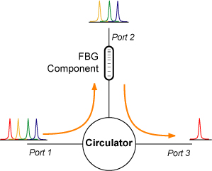
Consider a reflection-based optical sensing system:
A laser source launches light into Port 1.
The circulator directs the optical signal from Port 1 to Port 2.
An FBG sensor or another reflective element is connected to Port 2.
Reflected light returns to the circulator through Port 2.
The returning signal is routed to Port 3, where it can be measured by a detector.
This arrangement separates the launched signal from the returning signal while allowing both to share the same sensing fiber.
In a polarization-sensitive system, using a PM circulator also helps maintain the intended polarization orientation through the supported optical paths.
Note: Although simplified circulator diagrams sometimes show Port 3 → Port 1 as an additional cyclic path, many commercial three-port devices specify only Port 1 → Port 2 and Port 2 → Port 3. Do not assume that Port 3 → Port 1 is supported unless it is explicitly specified in the datasheet.
2.3 How Polarization Is Maintained
Polarization-maintaining fibers are intentionally birefringent, meaning that light polarized along two orthogonal principal axes experiences different effective refractive indices.
These axes are commonly called the slow axis and fast axis.
When linearly polarized light is launched along one principal axis, the PM fiber can maintain that polarization orientation with limited coupling into the orthogonal axis, provided that the fiber and its connections are properly handled.
A PM optical circulator is designed to preserve this controlled polarization behavior along its specified transmission path.
However, angular misalignment at connectors, splices, or internal optical interfaces can couple power into the orthogonal polarization mode and degrade the output polarization extinction ratio.
This is why working-axis compatibility is a critical specification when integrating a PM circulator into an optical system.
3. PM Optical Circulator vs. Polarization Insensitive Optical Circulator
Both polarization-maintaining and polarization insensitive optical circulators provide nonreciprocal signal routing. The primary difference is how they handle the polarization state of the transmitted light.
Feature | Polarization Maintaining (PM) | Polarization Independent (PI) |
|---|---|---|
Primary design objective | Preserve a specified polarization orientation | Provide stable routing for varying input polarization states |
Fiber type | Polarization-maintaining fiber | Typically standard single-mode fiber |
Input polarization | Must satisfy the specified working-axis requirements | Can vary within device specifications |
Key polarization parameter | Polarization extinction ratio (PER/ER) | Polarization-dependent loss (PDL) |
Axis alignment | Critical | Generally not required |
Typical applications | Fiber lasers, interferometers, precision sensing | Telecom networks, general optical routing, OTDR |
Best choice | When polarization orientation must be controlled | When polarization preservation is unnecessary |
A polarization insensitive circulator is designed to have relatively low polarization-dependent insertion loss. This means its transmission efficiency changes only slightly as the input polarization varies.
However, low PDL does not mean that the component preserves the input polarization orientation.
Conversely, a PM optical circulator is designed for a defined polarization arrangement, but this does not necessarily make it suitable for arbitrary or randomly changing input polarization states.
Which should you choose?
If your system uses PM fiber and requires a stable polarization reference, a PM optical circulator is generally the appropriate choice.
If the application only requires directional routing and does not depend on preserving polarization, a polarization insensitive circulator may be a more economical solution.
For a broader explanation of different optical circulator types, see FIRSOL's 3-Port Optical Circulator: Working Principle, Types, and Selection Guide.
4. Key Specifications of Polarization Maintaining Optical Circulators
Understanding the optical specifications is essential when selecting a PM circulator. Devices with the same nominal wavelength can differ significantly in insertion loss, isolation, polarization performance, and power handling.
4.1 Operating Wavelength
The operating wavelength defines the spectral range over which the circulator's optical performance is specified.
Common design wavelengths include 1064 nm, 1310 nm, 1480 nm, and 1550 nm. Broadband devices are also available for applications covering multiple wavelengths.
A circulator should be selected according to the complete operating wavelength range of the laser or optical system rather than its nominal center wavelength alone.
For example, a narrowband 1550 nm PM circulator is not automatically suitable for operation across the entire C+L band.
4.2 Insertion Loss (IL)
Insertion loss represents the optical power lost along a specified transmission path, such as Port 1 → Port 2.
It is expressed in decibels (dB), with a lower value indicating more efficient optical transmission.
High insertion loss reduces the optical power available to downstream components. In systems that route a signal through the circulator twice, such as reflective sensors, the loss from both transmission paths must be included in the optical power budget.
Connector and splice losses should also be considered.
4.3 Isolation
Isolation describes how effectively a circulator suppresses unwanted transmission between specified ports or in an undesired direction.
It is expressed in dB, with higher isolation generally indicating stronger suppression of the unwanted optical path.
High isolation can help reduce unwanted optical feedback, suppress leakage, and improve the separation of forward and backward signals.
Engineers should distinguish between minimum isolation over the operating wavelength range and peak isolation near the optimum wavelength. These are not interchangeable specifications.
4.4 Polarization Extinction Ratio (PER/ER)
Polarization extinction ratio is one of the most important specifications of a PM optical circulator.
PER describes the ratio of optical power in the desired polarization component to the power in the orthogonal polarization component.
For linear polarization, it can be expressed as:
PER (dB) = 10 log₁₀(Pdesired / Porthogonal)
A higher PER indicates better separation between the desired and unwanted polarization components.
For example, a PER of 20 dB corresponds to a desired-to-orthogonal polarization power ratio of 100:1.
However, the measured output PER depends not only on the circulator but also on the input polarization quality, fiber-axis alignment, pigtail handling, connector orientation, and measurement method.
Therefore, the extinction ratio specified in a datasheet should be evaluated together with its stated test conditions.
4.5 Return Loss (RL)
Return loss describes the amount of optical power reflected backward toward a source relative to the incident power.
Higher return loss indicates lower reflected power.
This is particularly important in fiber laser systems, coherent measurements, and other applications where unwanted back reflections can affect source stability or measurement performance.
Return loss and isolation are different parameters: return loss concerns reflections at optical interfaces, while isolation concerns transmission along undesired paths.
4.6 Channel Crosstalk
Channel crosstalk describes unwanted signal leakage between optical ports or paths.
For circulators whose datasheets express crosstalk as a positive suppression value, a higher value indicates better separation.
Crosstalk should not be confused with polarization extinction ratio.
Crosstalk concerns unwanted port-to-port optical leakage, whereas extinction ratio concerns unwanted polarization components.
4.7 Maximum Optical Power
The maximum optical power rating defines the qualified optical power that the device can handle under specified operating conditions.
For continuous-wave systems, the maximum CW optical power must be considered.
For pulsed laser applications, engineers should also verify pulse duration, pulse energy, repetition rate, peak power, and reflected-power conditions.
A circulator rated for a particular CW power level should not automatically be assumed suitable for pulsed operation with the same average optical power.
5. Working Axis: Slow Axis, Fast Axis, and Both Axes
The working axis is a particularly important selection parameter for PM optical circulators.
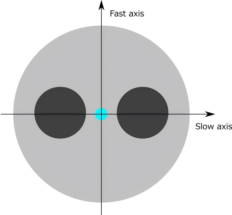
Slow Axis Working
In a slow-axis configuration, the device is optimized to operate with light polarized along the PM fiber's slow axis.
The input polarization must be aligned with the specified slow-axis orientation to obtain the intended polarization-maintaining performance.
For FIRSOL PM optical circulators, slow-axis operation is the standard configuration, and the fiber slow axis is aligned with the connector key by default.
This provides a defined polarization reference when the circulator is connected to other properly aligned PM fiber components.
Fast Axis Working
In a fast-axis configuration, the device is designed for operation with the input polarization aligned to the fast axis.
This option can be useful when the optical system uses the fast axis as its working polarization reference.
Fast-axis operation should be explicitly specified when ordering, rather than assumed from the connector type.
Both Axes Working
Some PM optical circulators are offered in both-axes working configurations.
These are intended to support operation on either principal polarization axis under the applicable device specifications.
However, both-axes working does not automatically mean that an arbitrary input polarization state will be preserved without change.
When a both-axes configuration is required, confirm the supported polarization states, insertion loss, extinction ratio, and operating conditions with the manufacturer.
Why Connector-Key Alignment Matters
Connector orientation is important because a PM connector provides a mechanical reference for the fiber's principal axes.
If two PM connectors are mated with incompatible axis orientations, the optical power may couple into both polarization modes, resulting in a reduced polarization extinction ratio.
Likewise, a PM fiber splice should maintain the intended relative orientation of the polarization axes.
Before integrating a PM circulator, verify the axis-to-key convention of every connected PM component.
6. Common Applications of PM Optical Circulators
6.1 Fiber Laser Systems
Fiber lasers frequently use polarization-maintaining components when controlled linear polarization is required.
PM circulators can route optical signals between different sections of a laser system, separate reflected light, and support polarization-sensitive feedback or measurement arrangements.
The required wavelength, optical power rating, insertion loss, and isolation should be considered together.
For high-power laser systems, a circulator must be explicitly qualified for the intended optical power and operating conditions.
6.2 Fiber Bragg Grating (FBG) Sensors
FBG sensors reflect a wavelength-dependent portion of an incident optical signal.
A PM circulator can direct light from a source to an FBG sensor through Port 1 → Port 2 and route the reflected signal from Port 2 → Port 3 toward a detector.
In polarization-sensitive FBG sensing systems, maintaining a controlled polarization state can help reduce polarization-related measurement variation.
The circulator itself does not provide wavelength-selective filtering; that function is performed by the FBG.
6.3 Interferometers and Precision Measurement
Interferometric systems measure the interference between optical signals traveling along different paths.
Polarization mismatch between the interfering signals can reduce interference visibility and affect measurement quality.
A PM optical circulator can provide directional signal routing while supporting a controlled polarization orientation in the optical path.
This makes it useful in selected interferometric sensors, precision measurement instruments, and polarization-sensitive laboratory systems.
6.4 Coherent Optical Systems
Coherent optical systems rely on controlled relationships between optical signals and a reference source.
In polarization-sensitive coherent architectures, PM optical components can help establish stable polarization references.
PM circulators may be used where the optical layout requires both nonreciprocal routing and polarization control.
However, not all coherent communication systems require PM circulators. Many polarization-diverse coherent receivers are designed to accommodate changing polarization states.
The choice depends on the system architecture.
6.5 Optical Amplifiers
Optical circulators can route forward and backward signals in selected optical amplifier configurations.
PM versions are useful when the amplifier system must preserve a defined polarization orientation.
Relevant selection parameters include the signal wavelength, optical power, reflected-power conditions, insertion loss, isolation, and compatibility with the amplifier's PM fiber.
6.6 Wavelength-Division Multiplexing Systems
An optical circulator can be combined with a fiber Bragg grating or another wavelength-selective reflective component to route selected wavelengths.
In a wavelength add/drop arrangement, a grating reflects the selected wavelength back toward the circulator, which directs the reflected channel to another port.
A PM optical circulator is appropriate when the wavelength-routing system also requires controlled polarization. For conventional polarization insensitive DWDM networks, a PI circulator may be more suitable.
7. How to Choose the Right PM Optical Circulator
A practical selection process should address the following requirements.
Step 1: Determine the operating wavelength.
Identify the center wavelength and the complete wavelength range of the optical source. Select a circulator whose specified operating range covers the application.
Step 2: Confirm the PM fiber type.
Match the circulator fiber with the optical system's wavelength and polarization requirements. Common PM fiber types include PM980, PM1300, and PM1550, depending on the product.
Step 3: Select the working axis.
Determine whether the system requires slow-axis, fast-axis, or both-axes operation. Confirm the axis-to-key orientation when using connectorized PM fiber components.
Step 4: Evaluate the required extinction ratio.
Determine the polarization performance required by the system, accounting for the source PER, connectors, splices, and other components in the optical path.
Step 5: Check insertion loss and isolation.
Include insertion loss for every required circulator pass in the system power budget. Confirm that the specified isolation and channel crosstalk meet the application's feedback and leakage requirements.
Step 6: Verify optical power compatibility.
Select a device with an appropriate CW or pulsed optical power rating. High-power applications may require additional review of reflected power, connectors, and environmental conditions.
Step 7: Choose the connector and pigtail configuration.
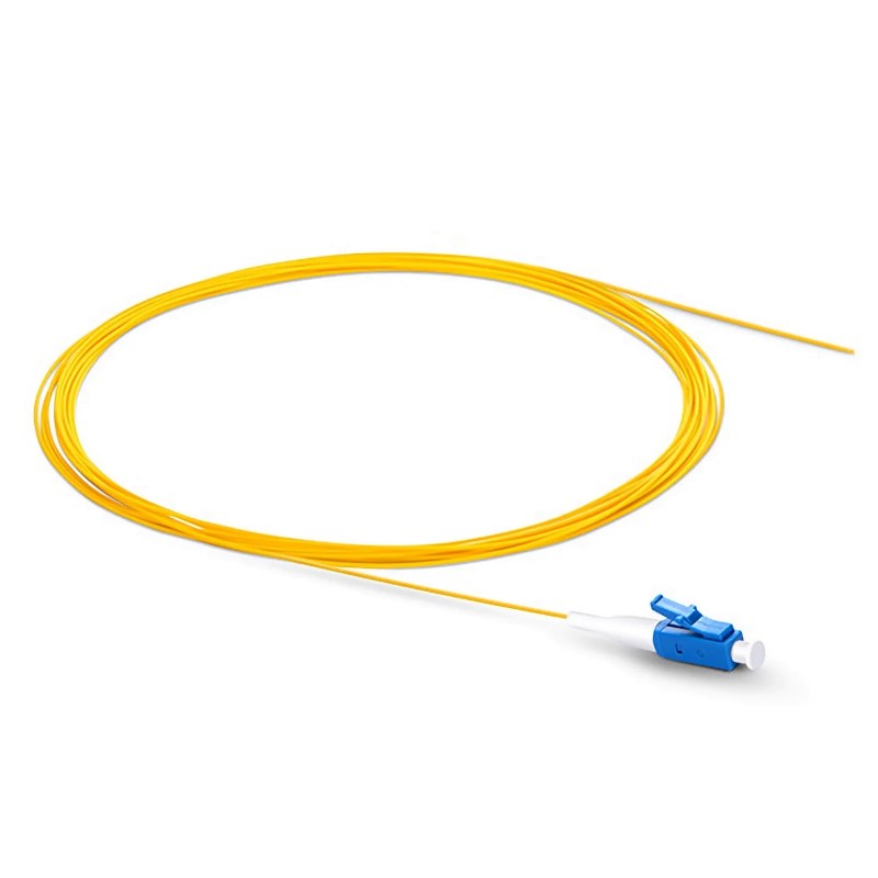
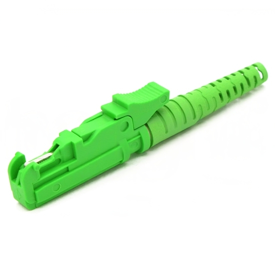
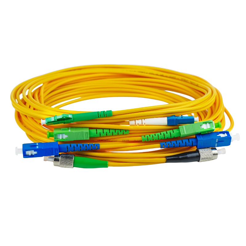
Available options may include bare fiber, 900 μm loose tube, different pigtail lengths, and connectorized assemblies such as FC/UPC or FC/APC.
For reflection-sensitive applications, APC connectors may be preferable because they are designed to reduce connector back reflections.
Step 8: Check the operating environment.
Confirm the required temperature range, package dimensions, mounting method, and any special mechanical requirements.
For custom optical systems, sharing the complete configuration with the manufacturer before ordering can help avoid fiber compatibility or polarization-alignment problems.
8. FIRSOL Polarization Maintaining Optical Circulator Options
FIRSOL provides 3-port PM optical circulators for a range of wavelengths, including 1064 nm, 1310 nm, 1480 nm, 1550 nm, and the 1528–1610 nm C+L band.
PM Optical Circulator | Fiber Type | Typical Application Considerations |
|---|---|---|
PM980 | 1064 nm fiber lasers and precision optical instruments | |
PM1300 | Polarization-sensitive systems around 1310 nm | |
PM1550 | 1480 nm optical systems and amplifier-related applications | |
PM1550 | Interferometry, sensing, and 1550 nm polarization-sensitive systems | |
PM1550 | Broadband C+L band polarization-sensitive optical routing |
Example: 1550nm PM Optical Circulator Specifications
The FIRSOL 1550nm Polarization Maintaining 3 Ports Optical Circulator (P/N: FIR-1550-PM-3P-OC) uses PM1550 fiber and a dual-stage optical design.
Its published specifications include:
Parameter | Specification |
|---|---|
Center Wavelength | 1550 nm |
Operating Wavelength Range | 1550 ± 30 nm |
Insertion Loss | ≤ 0.9 dB |
Peak Isolation | ≥ 52 dB |
Isolation | ≥ 40 dB |
Extinction Ratio | ≥ 20 dB |
Return Loss | ≥ 50 dB |
Crosstalk Suppression | ≥ 50 dB |
Fiber Type | PM1550 |
Working Axis | Slow Axis (Default); Fast Axis or Both Axes on request |
Note: These are published specifications measured at 25°C without connectors. Connectorized configurations can have higher insertion loss and lower extinction ratio and return loss. Verify the performance of the exact configuration before ordering.
FIRSOL also offers different optical power options, pigtail lengths, fiber protection styles, and connector configurations for selected models.
Explore the complete FIRSOL PM Optical Circulator product range for detailed specifications and available options.
9. Frequently Asked Questions
Q1. What is the main difference between a PM optical circulator and a standard optical circulator?
A PM optical circulator is designed to maintain a specified polarization orientation when the input light is correctly aligned with its working axis. A typical polarization insensitive circulator is designed for stable optical routing despite changes in input polarization, but it does not necessarily preserve a defined polarization orientation.
Q2. Can a PM optical circulator maintain any polarization state?
Not necessarily. A standard single-axis PM circulator is designed for a specified linear polarization orientation. Light launched at an angle to the principal axes can excite both polarization modes, potentially affecting the output polarization state and extinction ratio.
Both-axes configurations should be evaluated according to their specific design and guaranteed performance.
Q3. What does an extinction ratio of 20 dB mean?
A polarization extinction ratio of 20 dB corresponds to a 100:1 optical power ratio between the desired and orthogonal polarization components.
A higher extinction ratio generally indicates better suppression of the unwanted polarization component, although the actual output PER also depends on the source and the complete fiber assembly.
Q4. Does a higher isolation value mean a better PM optical circulator?
Higher isolation provides stronger suppression of the specified unwanted transmission path. However, isolation should not be evaluated alone.
Insertion loss, extinction ratio, operating wavelength, power handling, and working-axis compatibility are equally important for overall system performance.
Q5. Can a PM optical circulator be used with standard single-mode fiber?
It may be physically possible to connect a PM circulator to standard single-mode fiber when the wavelength and mode compatibility are appropriate.
However, standard single-mode fiber does not provide the same controlled polarization-axis behavior as PM fiber.
Therefore, the complete assembly may not maintain the intended polarization performance. PM fiber should generally be used throughout optical paths that require a defined polarization orientation.
Q6. Is a PM optical circulator the same as a PM optical isolator?
No. Both devices use nonreciprocal optical behavior, but their functions differ.
A PM optical circulator routes light between designated ports, allowing forward and reflected signals to be separated.
A PM optical isolator is primarily designed to transmit light in the forward direction while strongly attenuating unwanted reverse transmission.
If the backward signal must be measured or reused, a circulator is often appropriate. If the goal is simply to suppress optical feedback toward a laser source, an optical isolator may be a simpler solution.
Q7. Can I use a 1550nm PM optical circulator at 1310nm?
A circulator should only be operated within its specified wavelength range.
A device designed around 1550 nm is not automatically suitable for 1310 nm operation because its insertion loss, isolation, and polarization performance may change significantly outside the specified band.
Select a circulator designed and qualified for the required operating wavelength.
Q8. What information should I provide when ordering a customized PM optical circulator?
The most useful information includes the operating wavelength, required working axis, PM fiber type, minimum extinction ratio, insertion loss, isolation, maximum CW or pulsed optical power, pigtail length, connector type, and package requirements.
Providing these details allows the supplier to evaluate a configuration against the intended optical system rather than relying only on the nominal wavelength.
10. Conclusion
A polarization maintaining optical circulator is an important component in optical systems that require both nonreciprocal signal routing and controlled polarization performance.
Its ability to direct light from Port 1 to Port 2 and from Port 2 to Port 3, while maintaining the specified polarization orientation, makes it useful in fiber lasers, interferometers, FBG sensors, coherent systems, optical amplifiers, and precision instrumentation.
When selecting a PM optical circulator, the most important considerations are the operating wavelength, insertion loss, isolation, extinction ratio, working axis, PM fiber type, and optical power requirements.
A properly specified component can help maintain polarization consistency and provide reliable separation of forward and reflected optical signals.
Looking for a Polarization Maintaining Optical Circulator?
Explore FIRSOL Polarization Maintaining Optical Circulators or contact [email protected] for assistance with wavelength selection, working-axis requirements, connector configurations, and custom specifications.