How to Choose an MPO Cable: Polarity, Gender, Fiber Count, and Performance
Choosing an MPO cable requires more information than connector type and length. Two assemblies may both be described as “MPO-12 OM4 cables” while having different pin configurations, polarity maps, end-face polish, loss grades, and key orientations. One may work immediately; the other may fail to establish the required transmit-to-receive paths or may not mate safely with the equipment.
The safest method is to treat the MPO link as a complete channel. Start with the equipment interfaces and lane assignment, trace every fiber through the patch cords, adapters, trunks, and cassettes, and then specify each cable. This guide explains the selection process and the common mistakes to avoid.
If you are new to MPO connectivity, first read [What Is an MPO Connector? Types, Structure, MPO vs. MTP, and Applications].
The Seven Specifications to Confirm
Before ordering, confirm:
Equipment interface and optical standard
Fiber count and populated positions
Pinned or unpinned connector on each end
Polarity and fiber-position map
Fiber type: OS2, OM3, OM4, or OM5
UPC or APC polish
Standard-loss or low-loss performance grade
Also specify cable length, jacket rating, cable diameter, breakout construction, pulling eye if needed, and labeling requirements.
Step 1: Start with the Equipment Interface
Do not select an MPO cable from network speed alone. Two transceivers operating at the same aggregate data rate may use different optical architectures. One may use multiple parallel fibers through an MPO interface, while another may use wavelength division multiplexing over duplex LC connectors.
Record the following information for each end:
Equipment manufacturer and model
Transceiver model
Optical standard or application code
Port connector type
Fiber mode and wavelength
Number and direction of optical lanes
Maximum channel insertion loss
The module data sheet is more reliable than assumptions such as “all 400G uses MPO-16.” Once the required interface and lane map are known, the cable can be specified correctly.
Step 2: Select the Fiber Count
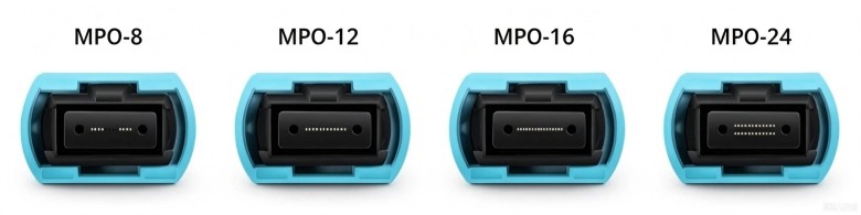
MPO-8 vs. MPO-12
Eight active fibers are commonly used for four-lane transmit and four-lane receive links. An eight-fiber assembly can provide full utilization in such a system. A 12-fiber trunk may also support an eight-fiber application by using selected positions and leaving four positions unused, depending on the architecture.
MPO-12 remains valuable for structured cabling because one trunk can transition to six duplex LC connections. MPO-8 is attractive when the infrastructure is designed around Base-8 parallel optics and minimizing unused fibers is a priority.
MPO-12 vs. MPO-16
MPO-16 contains 16 fibers in one row and uses offset keying. It is associated with interfaces requiring eight transmit and eight receive fibers. A conventional centered-key MPO-12 connector or adapter is not a substitute for an MPO-16 interface.
When planning a migration, confirm whether the new equipment requires an MPO-16 port, an eight-active-fiber interface in an MPO-12 footprint, or a duplex interface. These architectures cannot be inferred from “400G” or “800G” alone.
When MPO-24 Makes Sense
MPO-24 can reduce trunk count in high-density backbone installations. It is most useful when the patching and breakout architecture can use its two rows efficiently. It is less attractive when the project adds complex conversions or leaves many fibers unused.
Step 3: Choose Pinned or Unpinned MPO Connectors
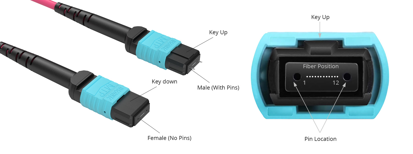
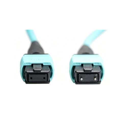
A pinned or “male” MPO has two guide pins. An unpinned or “female” MPO has guide holes.
Mating combination | Result |
Pinned + unpinned | Correct mechanical alignment when all other interface details match |
Pinned + pinned | Pins can collide; do not mate |
Unpinned + unpinned | No guide pins for precision ferrule alignment |
Active equipment commonly has pinned MPO receptacles, so a direct-attach patch cord normally uses an unpinned connector at the equipment end. Trunks and cassettes vary. Inspect the port or obtain the component specification before deciding.
The pin configuration on end A does not automatically determine end B. MPO assemblies can be pinned-to-pinned, unpinned-to-unpinned, or pinned-to-unpinned depending on where they sit in the channel. The correct choice is the one that provides one pinned and one unpinned interface at every mating point.
Step 4: Understand Key Orientation and Position 1
The connector key controls physical orientation. A white dot or triangle commonly identifies fiber Position 1. Both are important when reading a polarity diagram.
“Key up” and “key down” describe the key orientation when viewing the connector from a defined direction. Because diagrams can be drawn from the front, rear, or cable side, every drawing should include a viewing-direction label. A drawing without orientation can create the same mistake it is intended to prevent.
MPO-16 uses offset keying rather than the centered key used by conventional one-row MPO-12 hardware. Key location is therefore both a polarity feature and a physical compatibility check.
Step 5: Select the MPO Polarity
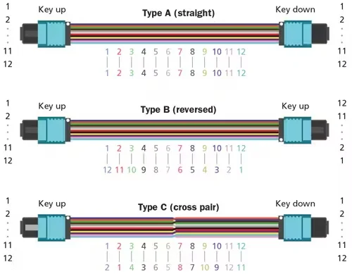
Polarity ensures that each transmitter at one end reaches the intended receiver at the other. In an MPO system, this depends on the fiber mapping inside each cable and cassette, the connector key orientation, and the patching arrangement.
The three commonly discussed methods are A, B, and C.
Method A: Straight-Through
In a Type A trunk, fiber positions remain straight through:
Position 1 → Position 1
Position 2 → Position 2
Position 3 → Position 3
and so on
The connectors are commonly described as key-up to key-down. In a duplex channel, a transmit/receive flip must be introduced elsewhere in the system, such as through the appropriate patch cord at one end.
Method A is straightforward for maintaining sequential fiber positions, but the complete channel still needs a defined Tx/Rx flip.
Method B: Reversed
In a 12-fiber Type B trunk, positions are reversed:
Position 1 → Position 12
Position 2 → Position 11
Position 3 → Position 10
and so on
It is commonly described as key-up to key-up. Method B is widely used for parallel-optics patching because it can map transmit positions at one end to receive positions at the other. However, whether a particular Type B assembly is correct still depends on the transceiver lane positions and every component in the channel.
Method C: Pair-Flipped
Method C flips adjacent fiber pairs:
Position 1 → Position 2
Position 2 → Position 1
Position 3 → Position 4
Position 4 → Position 3
and so on
It was developed for duplex applications over MPO trunks. It is not generally used as the trunk method for standard parallel-optics links because its pairwise mapping does not provide the required full-array reversal.
Method | Basic mapping | Common description | Typical role |
A | Straight: 1→1 | Key-up to key-down | Backbone architecture with Tx/Rx flip introduced elsewhere |
B | Reversed: 1→12 on a 12-fiber array | Key-up to key-up | Frequently used in parallel-optics channel designs |
C | Pair-flipped: 1→2, 2→1 | Key-up to key-down | Duplex pair management over an MPO trunk |
Important: “Type A, B, or C” describes a fiber map, not a universal recommendation for every link. Ask for a channel diagram that identifies each component and shows Position 1 at both ends.
Step 6: Select OS2, OM3, OM4, or OM5
The cable fiber must meet the transceiver's optical specification.
OS2 single-mode: Used for single-mode links and longer reaches. MPO APC is common, but the equipment interface must be confirmed.
OM3 multimode: Used in established short-reach data center applications.
OM4 multimode: Offers greater modal bandwidth than OM3 and is widely used for high-speed short-reach links.
OM5 multimode: Supports wideband multimode applications when specified by the system.
Do not choose a fiber solely from jacket color or a generic distance chart. The supported reach may change with the Ethernet variant, transceiver, wavelength, connector count, and channel loss.
Step 7: Select UPC or APC
Multimode MPO assemblies commonly use UPC polishing. Single-mode MPO interfaces frequently use APC to improve return loss. The mating interfaces must use the same compatible polish and angle orientation.
Never mate UPC to APC. Even if the connectors can be forced into an adapter, their end faces will not make the intended physical contact.
For APC assemblies, key orientation and angled-ferrule orientation are linked. Changing a connector key or polarity in the field is not automatically safe for every APC product. Use a connector specifically designed for reconfiguration and follow the manufacturer's procedure.
Step 8: Check the Insertion-Loss Budget
Every mated pair, cassette, splice, and length of fiber contributes loss. Parallel optical links can have relatively tight budgets, and all lanes must pass—not just the average lane.
Use the equipment's maximum channel loss as the starting point:
Available margin = Maximum permitted channel loss − Sum of planned component losses − Engineering margin
Choose a low-loss MPO assembly when the channel contains multiple mated pairs, cassettes, conversion points, or little remaining margin. “Low loss” and “elite” are not universal numerical grades across every supplier, so the purchase specification should state the maximum insertion loss per mated pair or per finished assembly, the return-loss requirement, and the required test report.
Ask whether the published loss is:
Typical or maximum
Per connector, mated pair, or complete assembly
Measured against a reference-grade connector
Specified for every fiber or as an average
Valid for the exact single-mode or multimode ferrule grade being supplied
Choose the Cable Construction
Once the optical design is correct, specify the mechanical construction.
Trunk cable
Use an MPO-to-MPO trunk between distribution points, panels, or cassettes. Confirm connector pulling-eye protection, fanout length, overall diameter, bend radius, and installation direction.
Direct-attach patch cable
Use an MPO patch cable for compatible equipment-to-equipment or equipment-to-panel connections. Confirm that both equipment ports, connector pins, polarity, and optical lane maps match.
Breakout or harness cable
Use an MPO-to-LC breakout when one MPO interface must connect to multiple duplex ports or when a trunk needs direct distribution without a cassette. Specify LC numbering and Tx/Rx mapping—not only the number of LC legs.
Conversion cable
Use a conversion assembly when the two sides use different fiber counts or lane groupings. Require a complete position-to-position map as part of the drawing and test documentation.
A Practical MPO Ordering Checklist
Use a line-item description that leaves as little room for interpretation as possible:
Application/transceiver:
End A connector and keying:
End A pinned or unpinned:
End B connector and keying:
End B pinned or unpinned:
Fiber count and populated positions:
Fiber type:
UPC or APC:
Polarity/fiber map:
Standard or low-loss grade:
Maximum insertion loss:
Return loss:
Cable length and tolerance:
Cable construction and diameter:
Jacket material and rating:
Fanout length:
Pulling eye:
Labeling:
Test report required:
Example:
12-fiber OM4 MPO cable assembly, unpinned to unpinned, Type B, UPC, low-loss grade, 10 m, LSZH jacket, with individual-fiber insertion-loss test report.
This example is not a universal configuration; it is a model for writing an unambiguous specification.
Common MPO Selection Mistakes
Selecting by data rate alone
“400G cable” is not a complete specification. Identify the optical standard, connector, fiber type, lane count, and reach.
Confusing gender with polarity
Pins control mechanical alignment. Polarity controls fiber routing. Changing one does not automatically correct the other.
Assuming an adapter changes polarity
An ordinary adapter aligns connectors; it does not reroute the fibers. Key orientation can influence how connectors face each other, but the fiber map remains determined by the assemblies and components.
Treating an MPO-12 and MPO-16 as interchangeable
Their fiber counts and keying interfaces differ. The connector, adapter, and equipment port must all match.
Ignoring the four unused positions
Some eight-active-fiber applications use an MPO-12 footprint with four positions unused. Confirm which positions are active and how they map at both ends.
Connecting two pinned connectors
Guide pins can collide and damage the ferrule. Inspect both ends before mating.
Mixing UPC and APC
Different end-face geometries can cause high loss and physical damage.
Ignoring cleanliness
Inspect before connecting, clean when necessary, and inspect again. Use tools designed for the connector's fiber count and pin configuration. A clean-looking housing does not prove the fiber end face is clean.
Comparing only typical loss values
Channel design should use guaranteed maximum values and include engineering margin.
Frequently Asked Questions
Which MPO polarity should I use for a direct connection between two parallel-optics transceivers?
Type B is commonly used for many direct parallel-optics connections because it reverses the array, but you must verify the transceiver's transmit and receive positions, connector interface, and fiber count. Do not order from the data rate alone.
Is an MPO transceiver port male or female?
Active equipment commonly presents a pinned interface, so the connecting cable is normally unpinned. Confirm the specific transceiver data sheet and inspect the port before mating.
Can a Type A cable be changed into Type B?
Some connector systems are designed for field polarity reconfiguration; others are not. APC ferrule angle, keying, pin configuration, product warranty, and the complete channel map must all be considered. Follow the connector manufacturer's approved method.
Can an MPO-12 cable be used with an eight-fiber transceiver?
Sometimes, if the connector interface and active fiber positions are compatible; four positions may be unused. An eight-fiber assembly or conversion solution may provide better utilization. Verify the equipment interface and position map.
Do I always need a low-loss MPO cable?
No. It depends on the channel budget and number of connections. Low-loss assemblies are valuable when the link has several mated pairs or tight margin, but the required maximum values should be calculated rather than selected from a label alone.
How do I verify MPO polarity after installation?
Use test equipment capable of identifying individual MPO fiber positions and verifying end-to-end mapping. Also measure insertion loss on every required lane and document the results.
Conclusion
Correct MPO selection begins with the optical interface and ends with a documented end-to-end fiber map. Confirm fiber count, pins, polarity, fiber type, polish, and loss grade before choosing the cable construction. If any of those details remain unknown, request the transceiver specifications and a connection diagram before production.
This approach prevents the most common MPO failures: incompatible keying, pin collision, Tx/Rx mismatch, unused or incorrectly mapped fibers, excessive loss, and UPC/APC mismatch.
Not sure which MPO cable matches your equipment? Send Firsol the transceiver models, port photos or data sheets, connection topology, required length, and installation environment. We can review the connector interface and prepare a fiber-position drawing for confirmation.