OS1 vs OS2 Fiber: What Is the Difference and Which Should You Choose?
OS1 and OS2 are both categories of single-mode fiber cabling commonly used in enterprise, campus, data center and telecommunications networks. They have similar nominal fiber dimensions and often use the same connectors, but they are not identical in performance.
The most important difference is attenuation. OS1 cabled fiber permits a maximum attenuation of 1.0 dB/km at 1310 nm and 1550 nm, whereas OS2 permits a maximum of 0.4 dB/km at 1310 nm, 1383 nm and 1550 nm. The lower loss and specified low-water-peak performance of OS2 make it the usual choice for new installations, longer links and wavelength-division multiplexing.
However, several common claims about OS1 and OS2 are misleading. OS1 is not necessarily limited to 10 Gb/s. OS2 is not always a loose-tube outdoor cable. OS1 and OS2 can generally be connected in the same single-mode link. Transmission distance is also determined by the optical transceivers and total channel loss—not by the OS category alone.
This guide explains those distinctions and provides a practical way to choose between OS1 and OS2 fiber.
OS1 vs OS2 at a Glance
Feature | OS1 | OS2 |
|---|---|---|
Optical fiber category | Single-mode | Single-mode |
Common nominal dimensions | 9/125 µm | 9/125 µm |
Maximum cabled attenuation | 1.0 dB/km | 0.4 dB/km |
Category test wavelengths | 1310 and 1550 nm | 1310, 1383 and 1550 nm |
Water-peak performance | Not specified at 1383 nm for legacy OS1 | Specified at 1383 nm |
Common cable construction | Traditionally tight-buffered indoor cable | Loose-tube, tight-buffered and other designs |
Typical use | Existing or short indoor building links | Indoor/outdoor backbones, campuses, FTTx, data center interconnects and telecom networks |
CWDM suitability | Verify the complete wavelength range first | Generally preferred, subject to the cable datasheet |
Choice for a new installation | Application-dependent | Usually recommended |
The attenuation figures above are category limits for cabled fiber. A manufacturer may offer cable with better typical or guaranteed performance, so the product datasheet should always be used for the final link calculation.
What Do OS1 and OS2 Mean?
“OS” stands for optical single-mode. OS1 and OS2 are performance categories for cabled optical fiber defined in structured cabling standards such as ISO/IEC 11801. This point matters because OS1 and OS2 do not simply describe the glass fiber by itself, nor do they define a connector, cable jacket or Ethernet speed.
ITU-T Recommendations use a different naming system. For example, ITU-T G.652 specifies the geometrical, mechanical and transmission characteristics of widely deployed dispersion-unshifted single-mode fiber. G.657 specifies bend-insensitive single-mode fiber. In comparison, OS1 and OS2 describe the attenuation performance expected after the fiber has been made into a cable.
Consequently, “OS2” and “G.652.D” are closely associated but are not interchangeable terms:
OS2 is a cabled-fiber performance category.
G.652.D is an ITU-T fiber and cable specification with low-water-peak requirements.
Modern OS2 cables commonly contain G.652.D fiber or bend-insensitive fiber that is compatible or compliant with G.652.D, such as certain G.657.A1 designs.
The current ISO/IEC cabling family also includes OS1a, which adds a 1383 nm requirement while retaining the 1.0 dB/km attenuation level. Because most buyers still compare OS1 and OS2, this article focuses on those two established categories, but checking the exact standard printed on a cable datasheet remains important.
What Is OS1 Fiber?
OS1 is a single-mode cabled-fiber category with a maximum attenuation of 1.0 dB/km at 1310 nm and 1550 nm. It has traditionally been associated with tight-buffered cable used inside buildings, including equipment rooms, riser pathways and building backbones.
In a tight-buffered cable, the coated fiber is surrounded by an additional protective buffer, commonly bringing the buffered fiber diameter to 900 µm. This construction makes individual fibers relatively easy to handle and terminate. Its installation advantages explain why it became common in premises cabling, but tight buffering is not the fundamental definition of OS1.
OS1 can still be suitable when:
An existing building already contains an OS1 cabling system.
The link is short and has sufficient optical power margin.
Only conventional 1310 nm or 1550 nm transmission is required.
The specified cable construction and fire rating meet the installation requirements.
Legacy OS1 cabling may not specify attenuation around 1383 nm. Older fiber can exhibit increased hydroxyl-ion absorption in this region, known as the water peak. That does not prevent normal 1310 nm or 1550 nm operation, but it can restrict the use of some CWDM wavelengths.
What Is OS2 Fiber?
OS2 is a lower-loss single-mode cabled-fiber category. Its maximum attenuation is 0.4 dB/km at 1310 nm, 1383 nm and 1550 nm. By controlling attenuation around the 1383 nm water-peak region, OS2 supports a broader usable wavelength range than legacy OS1 cabling.
OS2 is widely used for:
Building and campus backbones
Data center interconnects
Metropolitan and carrier networks
FTTx and passive optical networks
Long industrial or surveillance links
CWDM and other wavelength-division-multiplexing systems
OS2 was historically associated with loose-tube outside-plant cable. A loose tube isolates the coated fibers from mechanical stress and can incorporate water-blocking elements for outdoor environments. Nevertheless, OS2 is not limited to this construction. Tight-buffered OS2 patch cables, distribution cables and indoor/outdoor cables are readily available.
For a new single-mode installation, OS2 is generally the more practical choice because it provides lower loss, broader wavelength capability and more flexibility for later network upgrades.
Key Differences Between OS1 and OS2 Fiber
1. Attenuation and Link Margin
Attenuation describes how much optical power is lost as light travels through a cable and is expressed in decibels per kilometer. Lower attenuation leaves more of the transceiver’s optical power budget available for connectors, adapters, splices, splitters, aging and engineering margin.
Consider a simplified 2 km cable run calculated at the category limits:
OS1 cable loss: 2 km × 1.0 dB/km = 2.0 dB
OS2 cable loss: 2 km × 0.4 dB/km = 0.8 dB
In this example, OS2 preserves 1.2 dB more link margin. The complete channel calculation must still add the loss of every connector pair and splice, as well as any passive components and a suitable safety margin.
For a short patch cord, multiplying the attenuation coefficient by its length produces a very small number. Connector loss and workmanship normally dominate such a short assembly. This is why buyers should review both the fiber specification and the finished cable’s insertion-loss requirement.
2. Wavelength Range and the 1383 nm Water Peak
Both OS1 and OS2 are commonly used at 1310 nm and 1550 nm. The important distinction is that OS2 also has a defined attenuation limit at 1383 nm.
Traditional optical fiber could have a pronounced absorption peak near 1383 nm due to hydroxyl ions remaining in the glass. Low-water-peak manufacturing substantially reduces this loss and opens more of the spectrum between the conventional 1310 nm and 1550 nm windows.
This makes OS2 the safer choice for full-spectrum or expanded CWDM deployment. However, “OS2” should not replace proper wavelength verification. Before designing a WDM link, check the cable manufacturer’s guaranteed attenuation range, the operating wavelengths of every passive component and the transceiver specifications.
3. Tight-Buffered vs Loose-Tube Construction
A widely repeated rule says OS1 is tight-buffered and OS2 is loose-tube. This describes their historical use but is not an absolute purchasing rule.
Tight-buffered cable protects each fiber with a relatively thick buffer and is convenient for handling and direct termination. It is common in indoor distribution cables and patch cords.
Loose-tube cable places coated fibers inside one or more protective tubes, allowing the cable structure to isolate the glass from tensile, moisture and temperature-related stress. It is common in outside-plant and high-fiber-count cables.
An OS2 product can use either construction. The correct choice depends on where and how the cable will be installed—not simply on the OS2 label.
4. Indoor and Outdoor Applications
OS1 is traditionally used indoors, while OS2 is now used in both indoor and outdoor networks. Yet OS1/OS2 does not determine whether a cable is legally or mechanically suitable for a location.
For indoor installation, check the applicable jacket, flame and smoke requirements, such as OFNR, OFNP or an appropriate LSZH specification, according to the local code and project documents. For outdoor installation, examine UV resistance, water blocking, operating temperature, tensile strength, crush resistance, rodent protection and armor requirements. An indoor/outdoor cable may combine environmental protection with an indoor flame rating to reduce or eliminate transition splices.
5. Network Speed and Transmission Distance
OS2 has lower attenuation and therefore supports a larger loss budget over the same distance. But neither OS1 nor OS2 directly establishes the data rate or maximum link reach.
The real reach of a fiber link depends on:
The Ethernet, Fibre Channel, PON or transport interface
Transmitter output power and receiver sensitivity
Operating wavelength
Fiber attenuation and chromatic dispersion
Connector, adapter and splice losses
Passive components in the optical path
Required engineering and aging margin
For example, standards-based 40GBASE-LR4 and 100GBASE-LR4 interfaces are specified for 10 km over single-mode fiber, and industry Ethernet roadmaps identify both OS1 and OS2 as supported media for these applications. Therefore, saying that OS1 “cannot support 40G or 100G” is incorrect. Whether a particular installed OS1 channel passes depends on its length, condition and measured total loss.
Similarly, saying that every OS2 cable supports 200 km is misleading. A 200 km system requires optical equipment designed for that reach and may also require amplification or dispersion management. Replacing OS1 with OS2 does not turn a short-reach transceiver into a long-haul interface.
6. Cost and Availability
OS1 was historically considered the lower-cost option. Today, OS2 is produced at large scale and is the default single-mode choice for many patch cords and installation cables. The price difference can be small or nonexistent, depending on construction, fiber count, jacket, connector and order volume.
For a new network, selecting legacy OS1 merely to reduce the initial material cost can create limitations that outweigh a small saving. Existing OS1 does not automatically need replacement, however. If testing confirms that the link satisfies the application’s loss budget and wavelength requirements, it can remain in service.
Can OS1 and OS2 Fiber Be Connected?
Yes. OS1 and OS2 are generally physically compatible because both use standard single-mode fiber dimensions and the same families of single-mode connectors. They can be joined with a connectorized link or fusion splice when the relevant interface parameters are compatible.
There are several practical conditions:
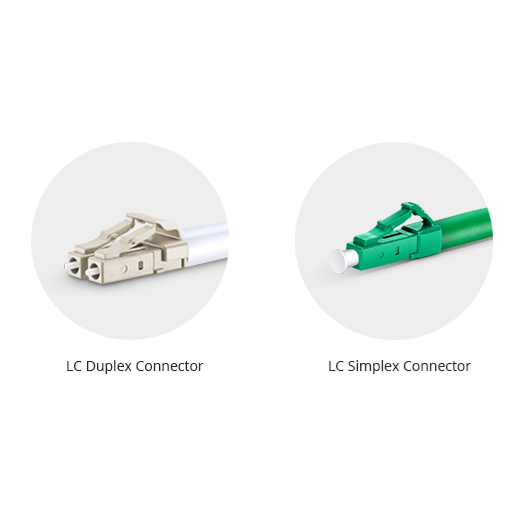
Match the connector type. LC, SC, FC and ST interfaces must be connected to the corresponding adapter or conversion assembly.
Match the end-face polish. UPC and APC connectors should not be directly mated because their end-face geometries are different. This issue is independent of OS1 and OS2.
Review fiber parameters. Differences in mode field diameter and other geometrical properties can add splice loss, particularly when joining dissimilar legacy and modern fibers.
Calculate the mixed link correctly. Use the specifications of each cable segment, and do not assume that adding an OS2 patch cord improves the performance of the existing OS1 backbone.
Verify the wavelength range. In a CWDM system, one legacy OS1 section with high water-peak attenuation can limit the entire path.
Testing the finished link with an optical loss test set is the best way to confirm channel loss. OTDR testing can additionally help locate unexpected events, poor splices or damaged cable sections.
How to Choose Between OS1 and OS2
Choose OS2 for Most New Installations
OS2 is usually the best default for new single-mode cabling. It offers lower attenuation, specified performance around 1383 nm and better flexibility for future optical interfaces or WDM expansion. This applies to data centers and indoor building backbones as well as campus and outside-plant networks, provided the selected cable has the correct construction and environmental rating.
Keep OS1 When an Existing Link Meets the Requirement
An operational OS1 link does not need to be replaced simply because OS2 is newer. Identify the transceiver specification, inspect the cable documentation and test the installed channel. If the measured loss and operating wavelength satisfy the application with adequate margin, retaining the existing cable may be the most economical decision.
Choose OS2 for CWDM and Broad Wavelength Use
When the link will carry CWDM channels near the water-peak region, select a cable with verified low-water-peak performance. OS2 is normally preferred, but the full cable datasheet should still be checked rather than relying on the category name alone.
Consider Bend-Insensitive OS2 in Dense Pathways
For high-density racks, crowded trays, FTTx drops and other areas where small routing radii are difficult to avoid, consider OS2 cable using suitable G.657.A1 or G.657.A2 bend-insensitive fiber. Confirm compatibility, minimum bend radius and application requirements before selecting the specific grade.
Specify More Than “OS2” on a Purchase Order
A complete cable specification should include:
OS category and, where appropriate, ITU-T fiber type
Fiber count and cable construction
Indoor, outdoor or indoor/outdoor environment
Jacket material and flame rating
Connector types and UPC or APC polish
Simplex, duplex or multi-fiber configuration
Required length and length tolerance
Maximum insertion loss and minimum return loss
Tensile, crush, bend-radius and temperature requirements
Test report and labeling requirements
This prevents an electrically correct but mechanically unsuitable product from being installed in the wrong environment.
Frequently Asked Questions
Is OS2 better than OS1?
OS2 provides lower specified attenuation and better coverage of the 1383 nm water-peak region, so it is generally the better choice for new installations. OS1 can still be adequate for an existing short indoor link that meets the required loss budget.
Are OS1 and OS2 both 9/125 µm?
They are both commonly described as 9/125 µm single-mode fiber systems: an approximately 9 µm core or mode-field region with 125 µm cladding. The exact mode field diameter is specified as a range and can vary by fiber design.
Can an OS2 patch cable be used on an OS1 link?
Yes, provided the connectors, polish type and other interface requirements match. The OS2 patch cable will not remove the attenuation or water-peak limitations of the installed OS1 portion.
Can OS1 support 40G or 100G Ethernet?
Potentially, yes. OS1 is not capped at 10 Gb/s. A link must meet the optical interface’s length, loss and dispersion requirements. Some standardized 40G and 100G single-mode interfaces explicitly support OS1/OS2 media.
Is every OS2 cable loose-tube?
No. OS2 describes cabled optical performance. OS2 products can be loose-tube, tight-buffered, ribbon or another construction appropriate to the application.
Can OS2 fiber be installed indoors?
Yes. Select an OS2 cable with the flame rating and construction required by the building code and pathway. OS2 patch cords and indoor distribution cables are common.
Is G.652.D the same as OS2?
No. G.652.D and OS2 belong to different classification systems. G.652.D specifies fiber and cable characteristics, while OS2 specifies a cabled-fiber performance category. G.652.D is nevertheless commonly used inside OS2 cables.
Does jacket color distinguish OS1 from OS2?
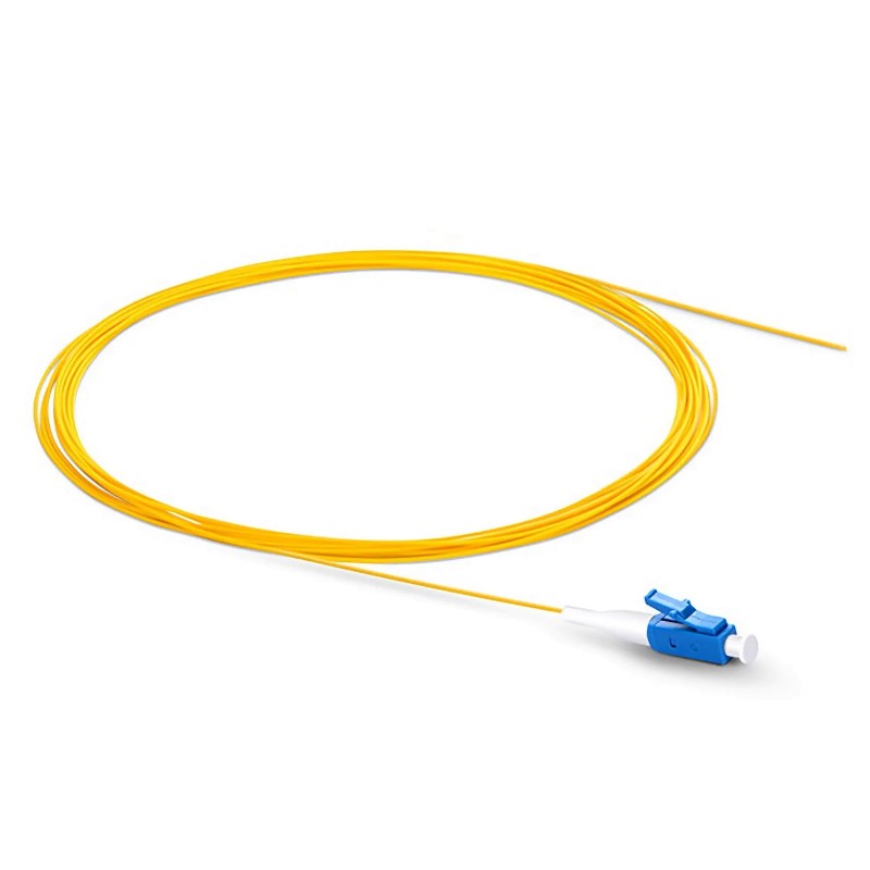
Not reliably. Both OS1 and OS2 single-mode cables are commonly yellow, and manufacturers may use other colors when properly identified. Read the jacket print and datasheet instead of relying only on color.
Conclusion
OS1 and OS2 are both single-mode cabled-fiber categories, but OS2 has a significantly lower attenuation limit and specified performance at the 1383 nm water peak. Those advantages make OS2 the preferred option for most new building backbones, campuses, data center interconnects, FTTx networks and WDM applications.
The decision should not stop at the category label. Network speed and reach come from the optical interface and complete link budget. Indoor or outdoor suitability comes from the cable construction, jacket and environmental ratings. OS1 and OS2 can usually coexist in one link, but the complete path must be calculated and tested according to its least-capable segment.
Firsol provides single-mode fiber optic cable solutions for patching, backbone, high-density and customized applications. Connector type, UPC or APC polish, fiber count, cable construction, jacket, length and performance requirements can be configured to match the project.