LC Fiber Connector Guide: Types, UPC vs APC, Applications and How to Choose
LC fiber connectors are widely used in data centers, telecommunications networks, enterprise cabling systems, fiber distribution frames, optical transceivers, and laboratory equipment. Their compact size allows network designers to install more fiber connections in a limited space, making LC one of the most common connector formats for modern high-density fiber networks.
However, not all LC connectors are the same. They may differ by fiber type, end-face polish, port configuration, cable construction, polarity, connector color, and application.
This guide explains what an LC fiber connector is, how different LC connector types compare, where they are used, and how to select the correct configuration for a fiber optic system.
What Is an LC Fiber Connector?
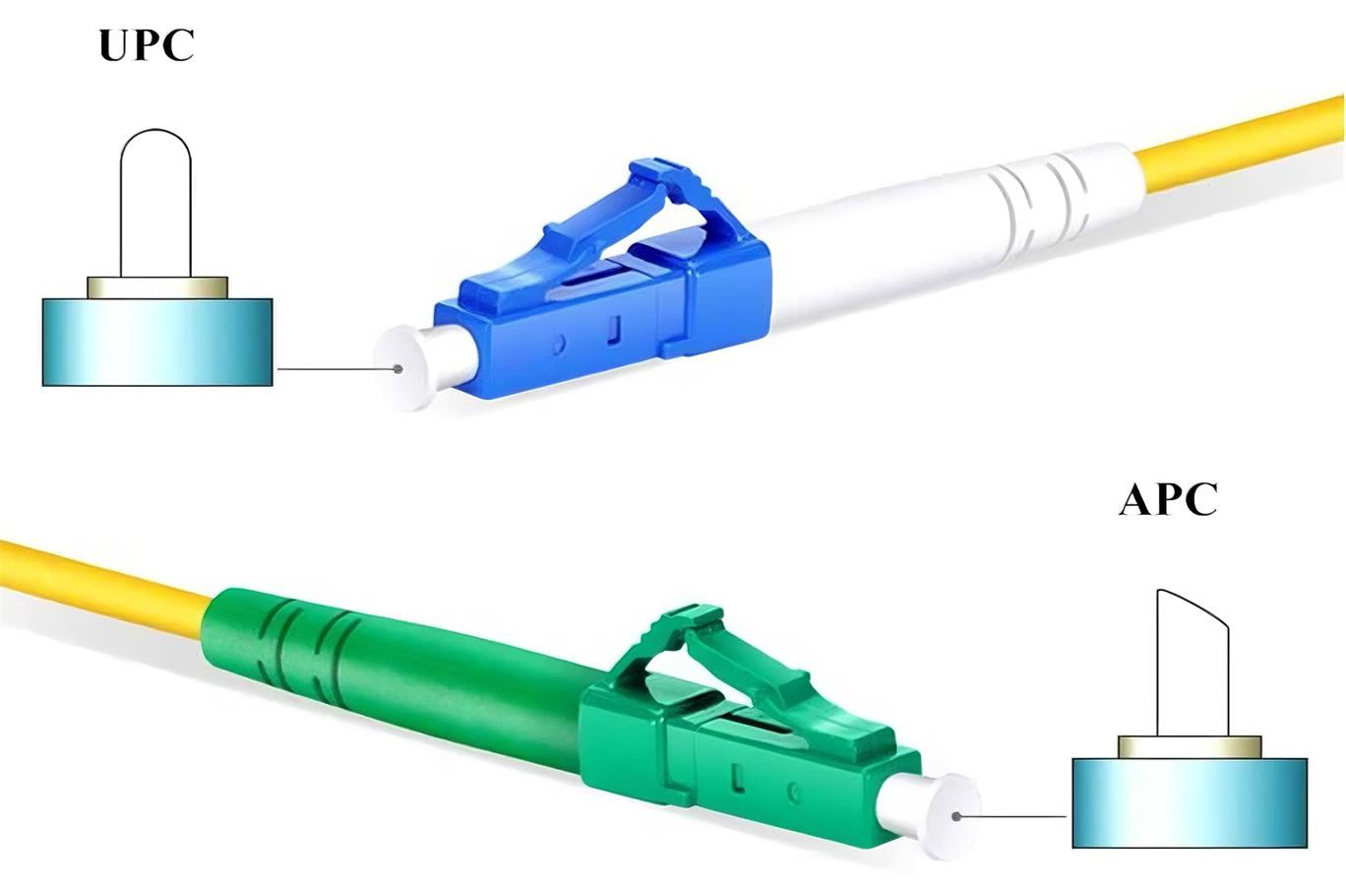
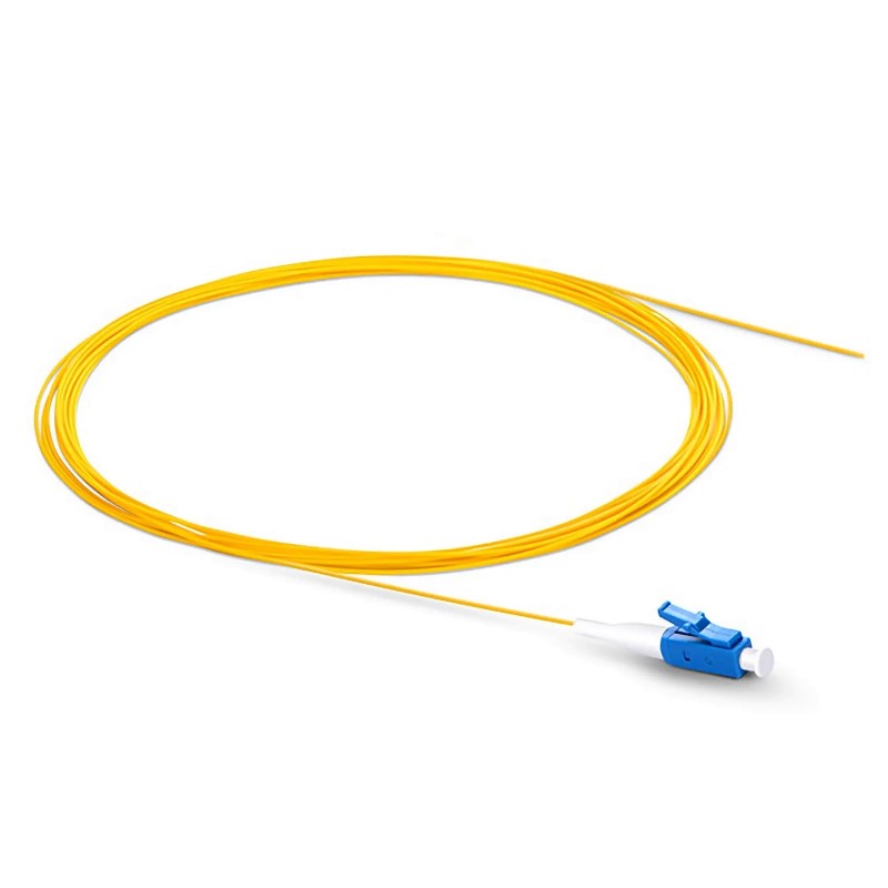
An LC fiber connector is a small-form-factor fiber optic connector that uses a 1.25 mm ferrule to align and connect optical fibers.
The term “LC” is commonly understood as Lucent Connector. Compared with connectors using a 2.5 mm ferrule, such as SC, FC, and ST connectors, the smaller LC ferrule allows a higher number of ports to be installed within the same panel or equipment space.
An LC connector normally includes:
A 1.25 mm ceramic ferrule
A connector housing
A latch mechanism
A strain-relief boot
A simplex body or duplex clip
A single-mode or multimode optical fiber
The latch design is similar to the locking tab found on an RJ45 Ethernet connector. It helps secure the LC connector inside an adapter, transceiver, patch panel, or other optical interface.
LC connectors can be used with both single-mode and multimode fibers and are available with UPC or APC polished end faces.
Main Features of LC Fiber Connectors
LC connectors are widely adopted because they provide several practical advantages.
Compact Size
The 1.25 mm ferrule and small connector body allow LC ports to be installed at a higher density than larger connector formats.
This is particularly useful in:
High-density patch panels
Data center racks
Optical distribution frames
SFP and SFP+ transceivers
Fiber cassettes
Network switches
Secure Latching Mechanism
The LC connector uses a push-and-latch locking design. The latch helps prevent the connector from becoming loose during normal equipment operation.
Single-Mode and Multimode Compatibility
LC connectors can be terminated on several fiber types, including:
OS2 single-mode fiber
OM1 multimode fiber
OM2 multimode fiber
OM3 multimode fiber
OM4 multimode fiber
OM5 wideband multimode fiber
The connector shape may be similar, but the fiber type, connector color, end-face polish, and optical performance must match the application.
Simplex and Duplex Configurations
LC connectors are available in simplex and duplex formats.
A simplex LC assembly contains one fiber and one connector at each end. A duplex LC assembly contains two fibers, normally used as separate transmit and receive channels.
UPC and APC Polish Options
Single-mode LC connectors are commonly available with UPC or APC polished end faces.
The required polish type depends on the equipment, return-loss requirement, optical power level, and application.
LC Fiber Connector Components
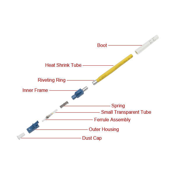
Understanding the main components of an LC connector can help when selecting connector parts or troubleshooting a damaged assembly.
Ferrule
The ferrule holds and aligns the optical fiber. LC connectors normally use a 1.25 mm zirconia ceramic ferrule.
The ferrule end face is polished to reduce optical reflection and insertion loss.
Connector Housing
The housing protects the ferrule and internal fiber. Connector housing colors are often used to identify the fiber or polish type, although color conventions can vary between manufacturers.
Latch
The latch secures the connector inside an LC adapter or equipment port. A damaged latch may cause an unstable connection even when the ferrule remains intact.
Duplex Clip
A duplex clip combines two simplex LC connectors into one duplex assembly. Depending on the design, the clip may allow polarity reversal or connector separation.
Strain-Relief Boot
The boot protects the fiber where it enters the connector. Different boot sizes are available for 900 μm buffered fiber and jacketed cables such as 2.0 mm or 3.0 mm patch cords.
Types of LC Fiber Connectors
LC connectors can be classified in several ways.
LC Single-Mode and Multimode Connectors
The connector must be matched with the fiber type used in the cable and optical system.
LC Single-Mode Connector
Single-mode LC connectors are commonly used with OS2 fiber in long-distance and high-bandwidth optical links.
Typical applications include:
Telecommunications networks
Data center interconnections
Passive optical networks
WDM systems
CATV networks
Optical test equipment
Fiber sensing systems
Single-mode connectors are usually available with either UPC or APC polish.
LC Multimode Connector
Multimode LC connectors are used with OM1, OM2, OM3, OM4, or OM5 fiber.
Typical applications include:
Short-distance data center links
Enterprise networks
Storage area networks
Equipment rooms
High-speed Ethernet connections
The correct multimode grade must be selected according to the transceiver, wavelength, transmission distance, and required data rate.
LC Simplex vs Duplex
One of the most important LC connector distinctions is simplex versus duplex.
Feature | LC Simplex | LC Duplex |
|---|---|---|
Number of fibers | One | Two |
Typical transmission | One optical path | Separate transmit and receive paths |
Connector arrangement | One LC connector | Two LC connectors joined together |
Common applications | BiDi systems, sensors, testing | Ethernet, switches, transceivers |
Polarity requirement | Usually simple | Tx and Rx polarity must be correct |
LC Simplex
A simplex LC patch cable contains one optical fiber. It is often used in:
BiDi transceiver systems
Optical sensing equipment
Laboratory instruments
Monitoring systems
Single-channel optical links
LC Duplex
A duplex LC patch cable contains two fibers. One fiber usually carries the transmit signal, while the other carries the receive signal.
Duplex LC connectors are frequently used with:
SFP transceivers
SFP+ transceivers
SFP28 transceivers
Network switches
Servers
Fiber media converters
Patch panels
When using duplex LC cables, polarity must be maintained so that the transmitting port at one end connects to the receiving port at the other end.
LC UPC vs LC APC
UPC and APC describe the geometry of the polished connector end face.
They are not interchangeable connector specifications.
LC UPC Connector
UPC means Ultra Physical Contact.
The ferrule end face is polished without the angled geometry used on an APC connector. LC UPC connectors are commonly identified by a blue housing when used with single-mode fiber.
LC UPC connectors are widely used in:
Data center networks
Ethernet equipment
Optical transceivers
Enterprise networks
General telecommunications systems
Test and measurement equipment
LC APC Connector
APC means Angled Physical Contact.
The ferrule end face is normally polished at an angle, commonly 8 degrees. This angled surface directs reflected light away from the fiber core, which helps improve return-loss performance.
LC APC connectors are commonly identified by a green housing.
They are often used in:
Passive optical networks
CATV systems
WDM systems
High-sensitivity optical equipment
Fiber sensing
High-power or reflection-sensitive optical systems
Analog optical transmission
LC UPC and LC APC Comparison
Feature | LC UPC | LC APC |
End-face geometry | Non-angled physical contact | Angled physical contact |
Common single-mode color | Blue | Green |
Reflection performance | Good | Better for reflection-sensitive systems |
Common applications | Ethernet, data centers, general networks | PON, CATV, WDM, sensing |
Direct mating compatibility | UPC to UPC | APC to APC |
An LC UPC connector should not be directly connected to an LC APC connector.
Although both use a 1.25 mm ferrule, the polished end faces do not match correctly. Directly mating UPC and APC connectors can create excessive insertion loss, poor return loss, and possible ferrule damage.
Standard LC, Uniboot LC and Push-Pull LC Connectors
LC connector assemblies are available in several mechanical designs.
Standard LC Duplex Connector
A standard duplex LC cable uses two individual connectors held together by a duplex clip.
This is a common and economical configuration for general network cabling.
LC Uniboot Connector
An LC uniboot cable places two fibers inside a single cable jacket. This reduces cable volume and can improve airflow and cable management in high-density racks.
Some uniboot designs also support polarity reversal without requiring the connector to be reterminated.
LC uniboot cables are commonly used in:
Data centers
High-density patch panels
Network switches
Server racks
Fiber cassettes
Push-Pull LC Connector
Push-pull LC connectors include an extended tab or housing that allows the connector to be inserted or removed without directly pressing the standard LC latch.
This is useful when connectors are installed in high-density ports with limited finger access.
Common LC Connector Color Conventions
Connector colors can help identify fiber and polish types, but color alone should not be used as the final specification.
Common conventions include:
Connector Color | Common Application |
Blue | Single-mode UPC |
Green | Single-mode APC |
Beige | OM1 or OM2 multimode |
Aqua | OM3 or OM4 multimode |
Lime green | OM5 multimode |
Color conventions may vary according to the manufacturer, cable design, or customer requirements. Always verify the product label and technical specification before installation.
Where Are LC Fiber Connectors Used?
LC connectors are found throughout modern optical networks.
Optical Transceivers
Many SFP, SFP+, SFP28, and other small-form-factor optical transceivers use duplex LC interfaces.
The compact connector size is well suited to high-density switch and server ports.
Data Centers
LC connectors are frequently used for:
Switch-to-switch connections
Server uplinks
Storage networks
Patch panel connections
Fiber cassette connections
MTP/MPO-to-LC breakout systems
Telecommunications Networks
Telecommunications operators use LC connectors in:
Optical distribution frames
Transmission equipment
WDM systems
Access networks
Equipment cabinets
Fiber patch panels
Enterprise Networks
LC patch cables connect switches, routers, media converters, patch panels, and other network equipment in enterprise buildings.
Fiber Test and Laboratory Systems
LC connectors may also be used with:
Optical power meters
Light sources
Optical spectrum analyzers
Optical switches
Fiber lasers
Sensors
Research equipment
For laboratory or precision optical systems, connector polish, return loss, insertion loss, fiber type, and polarization characteristics must be specified carefully.
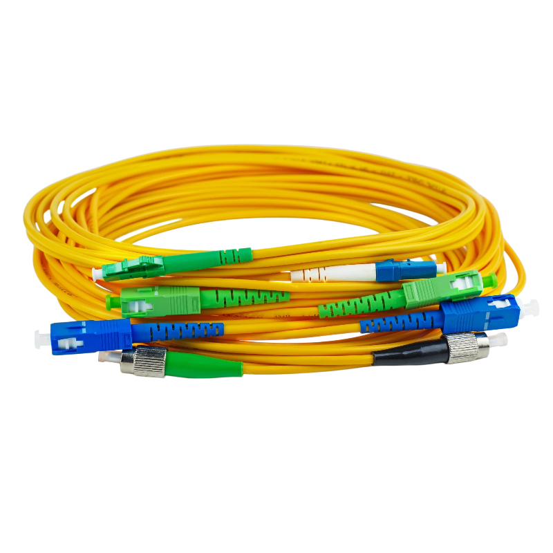
LC vs SC, FC and ST Connectors
LC is not the only fiber connector format. The correct choice depends on port density, mechanical stability, equipment compatibility, and application.
Connector | Ferrule Diameter | Locking Method | Main Advantage | Typical Application |
LC | 1.25 mm | Latch | High port density | Data centers, SFP transceivers |
SC | 2.5 mm | Push-pull | Easy installation | Telecom, enterprise networks |
FC | 2.5 mm | Threaded | Strong mechanical stability | Test equipment, laboratories |
ST | 2.5 mm | Bayonet | Simple locking mechanism | Legacy networks, industrial systems |
LC vs SC
LC is smaller than SC and allows more ports to be installed within the same panel space.
SC may be preferred where a larger connector body is easier to handle or where existing equipment already uses SC interfaces.
LC vs FC
FC connectors use a threaded coupling mechanism that provides strong mechanical stability.
They remain common in test systems, measurement equipment, fiber lasers, and laboratory applications. LC connectors are generally more suitable for high-density network equipment.
LC vs ST
ST connectors use a bayonet-style locking mechanism and are commonly found in older multimode networks and some industrial systems.
LC is more common in modern high-density Ethernet and data center installations.
How to Choose an LC Fiber Connector
Selecting an LC connector requires more than choosing the connector shape.
The following specifications should be confirmed before ordering.
1. Select the Fiber Type
Determine whether the system uses:
OS2 single-mode
OM1 multimode
OM2 multimode
OM3 multimode
OM4 multimode
OM5 multimode
The fiber type must match the transceiver, link design, operating wavelength, and required transmission distance.
2. Select UPC or APC
Use LC UPC when the equipment port is designed for UPC connections.
Use LC APC when the equipment requires APC connections or when improved reflection performance is necessary.
Never assume that UPC and APC ports can be mixed.
3. Select Simplex or Duplex
Choose simplex for single-fiber applications, including many BiDi systems.
Choose duplex when separate transmit and receive fibers are required.
4. Confirm the Connector at Both Ends
An LC cable does not need to use LC connectors at both ends.
Common configurations include:
LC to LC
LC to SC
LC to FC
LC to ST
LC to E2000
The polish type at each end must also be specified, such as LC/UPC to SC/APC.
5. Select the Cable Construction
Common options include:
Simplex cable
Duplex zipcord cable
Round duplex cable
Uniboot cable
Armored cable
Bend-insensitive cable
Breakout cable
Distribution cable
The required construction depends on installation space, mechanical protection, routing, and cable-management requirements.
6. Select the Cable Diameter
Common patch-cable diameters include:
0.9 mm
1.6 mm
2.0 mm
3.0 mm
Smaller cables save space, while larger cables may provide additional mechanical protection.
7. Select the Cable Jacket
Common jacket options include:
LSZH
OFNR
OFNP
PVC
TPU or other application-specific materials
The jacket must comply with the installation environment and applicable fire-safety requirements.
8. Confirm the Cable Length
The cable should be long enough to support proper routing without excessive tension.
At the same time, unnecessary excess length can increase congestion inside racks and cabinets.
9. Confirm Polarity
For duplex and multifiber systems, ensure the Tx and Rx channels are correctly mapped.
Polarity becomes especially important when using:
LC duplex assemblies
Uniboot cables
MTP/MPO-to-LC cassettes
Breakout cables
High-density structured cabling
10. Confirm Optical Performance
Depending on the application, specify requirements such as:
Maximum insertion loss
Minimum return loss
Operating wavelength
Repeatability
Durability
Fiber attenuation
Environmental temperature
Test report requirements
Performance limits should be evaluated for the complete cable assembly rather than the connector alone.
Can You Replace an LC Connector Yourself?
Whether an LC connector should be replaced depends on the type of cable and installation.
For Standard Patch Cables
For a short, removable LC patch cable, replacing the complete cable is often more practical than installing a new connector.
Factory-terminated patch cables are normally polished, inspected, cleaned, and tested before shipment. Replacing the entire cable can reduce the risk of excessive insertion loss, contamination, poor fiber alignment, or an unstable termination.
For Permanently Installed Fiber
Replacing the complete cable may not be practical when the fiber is:
Installed inside a building
Routed through conduit
Part of a long-distance backbone
Installed outdoors
Included in a high-fiber-count cable
Difficult to remove or replace
In these cases, a qualified technician may repair the link using:
Fusion-spliced pigtails
Mechanical splicing
Field-installable connectors
Connector retermination
The repaired link should be inspected and tested after the work is completed.
Tools Required for Field Termination
Depending on the termination method, technicians may require:
Fiber stripper
Precision cleaver
Connector installation tools
Cleaning materials
Fiber inspection microscope
Visual fault locator
Optical power meter and light source
Fusion splicer for pigtail splicing
Installing a connector without proper cleaning, cleaving, inspection, and testing can result in poor optical performance.
How to Clean an LC Fiber Connector
Connector contamination is one of the most common causes of fiber link failure.
Dust, oil, lint, and other particles can increase insertion loss, create reflections, or damage the ferrule end face.
A basic cleaning process normally includes:
Disconnect the fiber link safely.
Inspect the connector end face with an appropriate fiber inspection microscope.
Clean the connector using an LC-compatible cleaning pen or approved lint-free cleaning material.
Inspect the connector again.
Repeat the cleaning process when contamination remains.
Reconnect the fiber only after confirming that the end face is clean.
Avoid touching the ferrule end face with fingers.
Keep unused connectors and adapters protected with clean dust caps. A dust cap prevents general contamination, but it should not be assumed to make a connector permanently clean.
Common LC Connector Problems
Dirty Connector End Face
Contamination can cause high insertion loss, unstable performance, and reduced return loss.
Inspect and clean both sides of the connection before replacing equipment.
Broken Latch
A damaged latch may prevent the connector from remaining securely seated inside the port.
For removable patch cables, replacing the cable is normally the simplest solution.
Incorrect UPC and APC Connection
Connecting UPC and APC interfaces can produce poor optical performance and may damage the polished surfaces.
Verify connector color, port label, and technical documentation.
Incorrect Duplex Polarity
If the transmit channel is connected to another transmit channel, the link will not operate correctly.
Reverse the duplex polarity only when the cable and connector design support it.
Excessive Fiber Bending
Sharp bends can increase attenuation or permanently damage the fiber.
Maintain an appropriate bend radius during installation and cable management.
Damaged Ferrule
A scratched, chipped, or cracked ferrule should not be reused. Replace the connector or cable assembly.
Incorrect Fiber Type
An OS2 connector assembly should not be substituted for a multimode assembly without verifying the complete link design.
Likewise, different multimode fiber grades should not be mixed without considering transceiver compatibility and transmission performance.
Custom LC Fiber Connector and Cable Options
Firsol provides customizable LC fiber optic cable and connectivity solutions for telecommunications, data centers, enterprise networks, industrial systems, and laboratory applications.
Available configuration options include:
OS2 single-mode fiber
OM1 multimode fiber
OM2 multimode fiber
OM3 multimode fiber
OM4 multimode fiber
OM5 multimode fiber
LC UPC and LC APC connectors
Simplex and duplex assemblies
LC-to-LC cables
LC-to-SC cables
LC-to-FC cables
LC-to-ST cables
LC-to-E2000 cables
Standard and uniboot designs
Custom fiber length
Custom cable diameter
Custom cable jacket
Custom cable color
Custom polarity
Armored and bend-insensitive cable options
Connector type, fiber grade, cable construction, jacket material, length, polarity, and optical performance can be selected according to the application.
For custom LC fiber connector assemblies, provide the required fiber type, connector at each end, polish type, cable length, cable diameter, jacket, color, polarity, and quantity.
Frequently Asked Questions
What does LC stand for in fiber optics?
LC is commonly understood as Lucent Connector. It is a small-form-factor fiber connector that uses a 1.25 mm ferrule.
Is an LC connector single-mode or multimode?
LC describes the connector format, not the fiber type. LC connectors can be used with both single-mode and multimode fibers.
What is the difference between LC UPC and LC APC?
LC UPC uses a non-angled physical-contact polish, while LC APC uses an angled polish designed to reduce reflected light. They should not be directly connected to each other.
Can LC UPC connect to LC APC?
No. LC UPC and LC APC end faces have different geometries. Direct mating can cause high loss, poor return loss, and possible connector damage.
Is LC smaller than SC?
Yes. LC normally uses a 1.25 mm ferrule, while SC uses a 2.5 mm ferrule. The smaller LC connector supports higher port density.
What is an LC duplex connector?
An LC duplex connector assembly combines two LC connectors, normally used for separate transmit and receive fibers.
What color is an LC connector?
Common colors include blue for single-mode UPC, green for single-mode APC, beige for some multimode connectors, aqua for OM3 or OM4, and lime green for OM5. Color conventions should always be verified against the product specification.
Can a damaged LC connector be repaired?
It depends on the cable. A removable patch cable is often replaced completely. Permanently installed fiber may be repaired by a qualified technician using a field-installable connector, mechanical splice, or fusion-spliced pigtail.
How do I clean an LC connector?
Inspect the ferrule, clean it with an LC-compatible cleaning tool, and inspect it again before reconnecting. Do not touch the connector end face.
Where are LC connectors commonly used?
LC connectors are widely used in data centers, network switches, SFP transceivers, patch panels, telecommunications equipment, fiber cassettes, enterprise networks, and laboratory optical systems.
Conclusion
LC fiber connectors provide a compact and reliable connection format for modern single-mode and multimode fiber networks.
Choosing the correct LC connector requires confirming more than the connector name. Fiber type, UPC or APC polish, simplex or duplex construction, cable jacket, cable diameter, polarity, optical performance, and equipment compatibility must all be considered.
For standard patch cables, factory-terminated assemblies usually provide the most consistent installation and test performance. For permanent or specialized fiber links, connector repair or retermination should be completed by trained technicians with appropriate inspection and test equipment.
Firsol supplies standard and customized LC fiber optic cables, connector components, adapters, and related connectivity products for data centers, telecommunications networks, enterprises, manufacturing systems, and research laboratories.