What Is a Bare Fiber PLC Splitter? Types, Specifications, Applications & Selection Guide
A bare fiber PLC splitter is a compact passive optical component used to divide one or more optical input signals among multiple output fibers. Unlike PLC splitters packaged with 900 µm tubing, ABS housings, cassettes, or rack-mount enclosures, a bare fiber PLC splitter typically uses 250 µm coated fiber leads and a very small protective package.
This compact construction makes it particularly suitable for fusion splicing, fiber distribution assemblies, optical modules, FTTH/PON networks, and OEM equipment where installation space is limited.
Bare fiber PLC splitters are available in configurations such as 1×2, 1×4, 1×8, 1×16, 1×32, 1×64, and 2×N. However, choosing the correct splitter involves more than selecting the number of output ports. Engineers also need to consider insertion loss, loss uniformity, fiber type, wavelength range, package dimensions, fiber length, connector requirements, and the total optical power budget of the network.
This guide explains how bare fiber PLC splitters work, what “bare fiber” actually means, how they differ from other PLC splitter packages, and how to choose the right configuration for an optical network or equipment design.
What Is a Bare Fiber PLC Splitter?
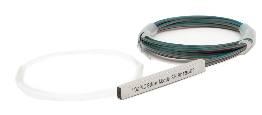
PLC stands for Planar Lightwave Circuit. A PLC splitter uses an optical waveguide circuit fabricated on a planar substrate to distribute optical power from one or more input ports to multiple output ports.
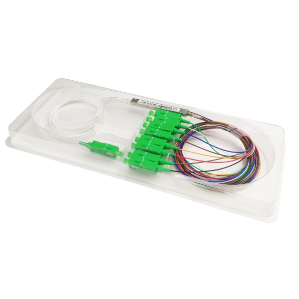
In a typical 1×N PLC splitter, light enters through one input fiber, passes into the PLC waveguide chip, and is divided into N output channels. A 1×8 splitter, for example, distributes one input signal among eight output fibers.
The term bare fiber PLC splitter refers primarily to the way the optical fibers and splitter assembly are packaged. Instead of using thicker buffered fiber, reinforced cable, or a large external enclosure, the splitter is supplied with thin 250 µm coated fiber leads.
This gives the device an extremely compact footprint and allows it to be integrated directly into splice trays, optical modules, fiber distribution equipment, and custom assemblies.
Bare fiber PLC splitters are therefore particularly useful when the splitter will be installed by an equipment manufacturer or technician rather than repeatedly connected and disconnected by an end user.
What Does “Bare Fiber” Actually Mean?
The term “bare fiber” can cause some confusion.
In the context of a bare fiber PLC splitter, it generally does not mean that the entire fiber lead is unprotected 125 µm glass with no coating. Instead, the commonly used industry term refers to 250 µm coated optical fiber without an additional 900 µm buffer, 2.0 mm jacket, or 3.0 mm cable jacket.
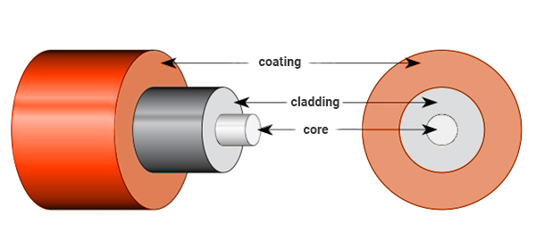
A typical single-mode optical fiber consists of a glass core and cladding surrounded by a protective primary coating. The coated fiber diameter is approximately 250 µm.
Therefore:
Fiber Description | Typical Construction |
|---|---|
125 µm fiber | Glass cladding diameter |
250 µm bare/coated fiber | Glass fiber plus primary coating |
900 µm buffered fiber | 250 µm fiber plus additional buffer |
2.0/3.0 mm cable | Buffered fiber plus strength members and outer jacket |
This distinction matters during installation.
A 250 µm fiber offers excellent space efficiency, but it does not have the same mechanical protection as 900 µm buffered fiber or jacketed cable. It therefore needs to be routed and handled carefully inside a protected enclosure, splice tray, or optical module.
How Does a Bare Fiber PLC Splitter Work?
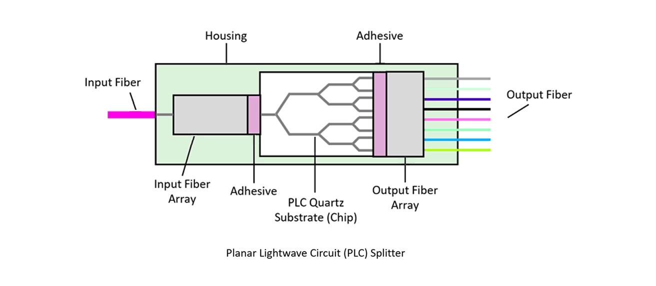
The optical operating principle of a bare fiber PLC splitter is essentially the same as that of other PLC splitter package types.
The assembly normally contains an input fiber, PLC optical waveguide chip, output fiber array, and protective package.
Light from the input fiber is coupled into the PLC chip. Inside the chip, a network of optical waveguides divides the incoming optical power into multiple paths. The output waveguides are aligned with the output fiber array, allowing the divided signals to leave through the individual output fibers.
For an ideal equal-ratio splitter, optical power is divided equally among the output ports.
The theoretical splitting loss can be estimated using:
Splitting Loss = 10 × log10(N)
where N is the number of equal output channels.
Configuration | Ideal Power per Output | Theoretical Splitting Loss |
|---|---|---|
1×2 | 50% | 3.01 dB |
1×4 | 25% | 6.02 dB |
1×8 | 12.5% | 9.03 dB |
1×16 | 6.25% | 12.04 dB |
1×32 | 3.125% | 15.05 dB |
1×64 | 1.5625% | 18.06 dB |
These values represent only the theoretical splitting loss.
A real PLC splitter has additional optical losses caused by the waveguide structure, fiber-to-chip coupling, manufacturing tolerances, splices, and other factors. For network design, the splitter's specified maximum insertion loss should therefore be used rather than the theoretical value alone.
The total optical power budget should also include fiber attenuation, connector loss, splice loss, and an appropriate engineering margin.
Common Bare Fiber PLC Splitter Configurations
Bare fiber PLC splitters are commonly produced in both 1×N and 2×N configurations.
A 1×N splitter has one optical input and multiple outputs. It is the most common configuration for optical distribution applications.
A 2×N splitter has two input fibers feeding the splitter network and multiple output ports. It can be used in optical architectures that require two input paths or other specialized distribution arrangements.
FIRSOL currently offers bare fiber PLC splitter configurations including:
Configuration | Number of Inputs | Number of Outputs |
|---|---|---|
1×2 | 1 | 2 |
1×4 | 1 | 4 |
1×8 | 1 | 8 |
1×16 | 1 | 16 |
1×32 | 1 | 32 |
1×64 | 1 | 64 |
2×2 | 2 | 2 |
2×4 | 2 | 4 |
2×8 | 2 | 8 |
2×16 | 2 | 16 |
2×32 | 2 | 32 |
For most equal-splitting applications, increasing the number of output channels also increases insertion loss. Port count should therefore be selected according to both the required number of branches and the available network optical power budget.
For example, a network should not automatically use a 1×64 splitter simply because more output ports are available. If only 16 branches are required, a lower split ratio may provide greater optical margin and simplify system design.
Key Specifications of a Bare Fiber PLC Splitter
A PLC splitter should not be evaluated only by its split ratio. Several optical specifications determine how it will perform in an actual system.
Operating Wavelength
The operating wavelength range defines the wavelengths over which the splitter is designed to meet its specified optical performance.
FIRSOL's standard single-mode bare fiber PLC splitter platform operates across 1260–1650 nm, covering commonly used wavelengths in PON, FTTH, telecommunications, CATV, and optical distribution systems.
A wide operating wavelength range is one of the advantages of PLC technology when optical signals at multiple wavelengths must pass through the same passive distribution network.
Insertion Loss
Insertion loss is one of the most important parameters when selecting a PLC splitter.
It represents the optical power reduction between an input port and a specified output port and is expressed in decibels.
Insertion loss includes the unavoidable loss caused by dividing the optical power as well as additional excess losses within the component.
For example, FIRSOL's standard specifications differ according to split ratio: a 1×2 splitter has much lower insertion loss than a 1×8, 1×16, or 1×32 splitter because the input optical power is distributed among fewer output channels.
When calculating an optical network, always use the maximum insertion-loss specification for the actual splitter model rather than assuming the theoretical splitting loss.
Loss Uniformity
Loss uniformity indicates the difference in insertion loss between the highest-loss and lowest-loss output channels.
For an equal-ratio splitter, lower loss uniformity means the output channels are more closely matched.
This parameter becomes increasingly important as port count increases because large output-to-output differences can create unequal optical power margins among network branches.
Polarization Dependent Loss
Polarization Dependent Loss (PDL) describes how much the insertion loss changes with the polarization state of the input light.
Low PDL helps provide consistent optical performance when the polarization state varies during normal system operation.
Return Loss
Return loss indicates how much optical power is reflected back toward the source.
Higher return loss generally means lower reflected optical power. Controlling reflections is important in optical communication systems because excessive back reflection can degrade system performance, particularly in systems using sensitive laser sources.
Directivity
Directivity describes isolation between optical paths within the splitter.
A higher directivity value indicates lower unwanted optical coupling between ports.
Wavelength Dependent Loss
Wavelength Dependent Loss, or WDL, describes how insertion loss changes across the specified operating wavelength range.
Low WDL is particularly useful in broadband passive optical networks where multiple optical wavelengths may travel through the same splitter.
Fiber Type
FIRSOL bare fiber PLC splitters use G.657.A1 bend-insensitive single-mode fiber.
Bend-insensitive fiber is well suited to compact fiber management environments because it provides improved bending performance compared with conventional single-mode fiber when routed through limited spaces.
This does not remove the need to follow appropriate bend-radius and handling requirements, but it provides greater design flexibility inside compact enclosures and optical assemblies.
Why Use a 250 µm Bare Fiber PLC Splitter?
The main advantage of a 250 µm bare fiber PLC splitter is integration density.
Without a 900 µm buffer or larger cable jacket around each lead, many fibers can be routed through a comparatively small space. This becomes particularly important with high-port-count devices such as 1×16, 1×32, and 1×64 splitters.
The compact construction also makes bare fiber PLC splitters attractive for OEM applications where the splitter is only one component inside a larger finished assembly.
However, the same construction creates an important trade-off.
The thin fibers require greater care during handling and installation. They are normally installed in a protected environment and should not be treated like ruggedized patch cables.
A bare fiber PLC splitter is therefore most appropriate when compact size and integration flexibility are more important than external mechanical protection.
Bare Fiber PLC Splitter vs. Blockless PLC Splitter
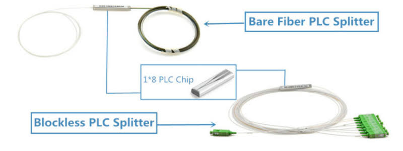
Bare fiber and blockless PLC splitters use similar optical splitting technology, but the fiber protection and intended installation method differ.
In the fiber optic market, “blockless” and “mini module” are often used for the same or very similar compact steel-tube PLC splitter package style. Supplier terminology is not completely consistent, so the actual mechanical drawing, fiber protection, dimensions, and lead construction should always be checked rather than relying only on the package name.
Feature | Bare Fiber PLC Splitter | Blockless / Mini Module PLC Splitter |
|---|---|---|
Typical fiber protection | 250 µm coated fiber | Usually additional buffered protection |
Package size | Extremely compact | Compact |
Fiber handling | Requires greater care | More mechanically protected |
Fusion splicing | Well suited | Well suited |
Installation space | Minimum | Slightly greater |
Typical installation | OEM modules, compact assemblies, protected splice areas | Splice trays, distribution boxes, compact network enclosures |
Connector options | Usually unterminated; customization possible | Unterminated or connectorized options may be available |
Neither package is universally better.
If minimum space and maximum integration flexibility are the priority, a bare fiber splitter is usually the better choice.
If additional mechanical protection is important while retaining a compact module, a blockless or mini-module design may be more suitable.
Bare Fiber vs. ABS Box, Cassette, and Rack-Mount PLC Splitters
The same basic PLC splitting function can be supplied in very different package formats.
A bare fiber PLC splitter sits at the compact end of the spectrum, while ABS box, cassette, and rack-mount products provide progressively more mechanical protection and easier field connectivity.
Package Type | Main Advantage | Typical Use |
|---|---|---|
Bare Fiber | Minimum size | OEM integration, compact optical assemblies |
Blockless / Mini Module | Compact with additional protection | Splice trays and distribution boxes |
ABS Box | Stronger cable protection | FTTx boxes and outdoor/indoor distribution equipment |
Cassette / LGX | Organized connectorized deployment | Patch panels and distribution frames |
Rack Mount | High accessibility and fiber management | Equipment rooms and central offices |
Package selection should therefore be based on the installation environment rather than optical performance alone.
If a splitter will be permanently fusion-spliced inside a protected device, there may be little benefit in using a large connectorized enclosure.
If technicians need to frequently connect, disconnect, test, or replace branches, a connectorized cassette or rack-mount design may be more practical.
Where Are Bare Fiber PLC Splitters Used?
FTTH and Passive Optical Networks
PLC splitters are widely used in FTTH, GPON, EPON, XG-PON, XGS-PON, and other passive optical distribution networks to divide a feeder fiber among multiple optical network terminals or downstream branches.
Bare fiber versions are particularly useful when the splitter is integrated into a splice tray, closure, terminal box, or custom optical distribution assembly.
The appropriate split ratio depends on the network architecture and optical power budget.
Fiber Distribution Equipment
Bare fiber PLC splitters can be built directly into fiber distribution boxes, closures, termination equipment, and other assemblies during manufacturing.
Because the fiber leads are compact, high port counts can be routed without requiring the space needed for individually jacketed cables.
OEM Optical Modules
Equipment manufacturers may integrate a PLC splitter into a larger optical subsystem instead of installing a complete standalone splitter enclosure.
A small bare fiber package provides greater mechanical design freedom and allows the manufacturer to determine the final fiber routing, connector type, cable protection, and enclosure.
Telecommunications and CATV Systems
PLC splitters can also be used wherever one optical source must be distributed among several optical paths, provided that the wavelength range, optical power, insertion loss, and environmental specifications meet the system requirements.
Test and Laboratory Assemblies
Bare fiber splitters may be integrated into permanent or semi-permanent optical test assemblies where compact passive signal distribution is required.
For temporary bench setups where connections are frequently changed, however, connectorized splitters may be more convenient.
How to Choose the Right Bare Fiber PLC Splitter
Selecting a bare fiber PLC splitter should begin with the network design rather than the splitter itself.
1. Determine the Required Split Ratio
Start with the number of optical branches required.
If eight outputs are required, a 1×8 splitter normally provides a more logical solution than installing a 1×16 splitter and leaving half of the outputs unused.
Higher split ratios result in greater optical loss, so unnecessarily increasing the port count reduces the available system power margin.
2. Check the Optical Power Budget
Calculate the complete optical path, including:
transmitter power → fiber attenuation → connectors → splices → PLC splitter → receiver sensitivity → system margin
Do not base the calculation only on theoretical splitting loss.
Use the maximum specified insertion loss of the actual splitter configuration, and include all other passive losses in the link.
3. Choose 1×N or 2×N
A standard distribution system normally uses a 1×N configuration.
A 2×N design should be selected only when the network architecture specifically requires two input paths or another dual-input arrangement.
4. Confirm the Fiber Type
Check that the splitter fiber is compatible with the rest of the optical network.
FIRSOL standard bare fiber PLC splitters use G.657.A1 bend-insensitive single-mode fiber, making them suitable for many compact single-mode distribution applications.
5. Select the Fiber Length
The fiber lead must be long enough to reach the planned splice or termination point without excessive tension.
FIRSOL bare fiber PLC splitters are available with common pigtail lengths including 0.5 m, 1.0 m, 1.5 m, and 2.0 m.
Choosing an unnecessarily long fiber can make fiber management more difficult, while a lead that is too short may make installation impossible.
6. Decide Whether Connectors Are Required
Bare fiber PLC splitters are naturally suited to fusion-spliced installations and are commonly supplied without connectors.
However, some projects require terminated input or output leads.
FIRSOL allows connector configuration options including common LC, SC, FC, and ST interfaces in UPC or APC versions, depending on the selected configuration.
If the product is intended primarily for direct connector access rather than fusion-spliced integration, it may also be worth considering whether another PLC splitter package type would provide better mechanical protection.
7. Check Mechanical Dimensions
Mechanical dimensions are especially important in OEM equipment and densely packed enclosures.
For example, standard FIRSOL 1×2, 1×4, and 1×8 bare fiber PLC splitters use a compact 40 × 4 × 4 mm package.
Always check the drawing for the exact splitter being specified, particularly when replacing a splitter from another supplier.
Two products described by similar package names may still have different body dimensions, fiber exit arrangements, and installation requirements.
8. Check Environmental and Power Requirements
Operating temperature, storage temperature, optical power handling, and installation environment should also be verified.
FIRSOL's standard bare fiber PLC splitter platform is specified for up to 500 mW optical power, with model-specific performance available in the corresponding product datasheets.
For unusual optical power levels or environmental conditions, confirm compatibility before installation.
Handling and Installing a Bare Fiber PLC Splitter
Because the fiber leads are thin, correct handling is important.
The splitter body should be secured inside the enclosure or equipment so that mechanical forces are not transferred directly to the fibers. Fibers should be routed with smooth bends and should not be sharply folded, pinched, twisted, or pulled.
During fusion splicing, only the required section of coating should be removed. The finished splice should be protected using a suitable splice protection sleeve and positioned correctly inside the splice tray or fiber-management system.
Excess fiber should be stored using an appropriate bend radius rather than tightly coiled into the smallest possible space.
High-port-count splitters also require organized fiber identification. Clear numbering and labeling of output fibers can significantly reduce installation and maintenance errors in 1×16, 1×32, and larger assemblies.
The key principle is simple: the bare fiber package saves space, but the final equipment must provide the mechanical protection that a larger cable jacket would otherwise provide.
Common Mistakes When Selecting a Bare Fiber PLC Splitter
A common mistake is choosing a splitter based only on price or port count.
For example, two 1×8 PLC splitters may appear interchangeable while having different insertion-loss limits, fiber types, body dimensions, fiber lengths, connector configurations, or environmental specifications.
Another mistake is assuming theoretical splitting loss is the same as actual device insertion loss. The theoretical value represents ideal optical power division and does not include all practical device losses.
Package terminology can also cause confusion. Terms such as bare fiber, blockless, mini module, and steel tube are sometimes used differently among manufacturers. Mechanical drawings and actual construction should be checked before approving an alternative product.
Finally, using a bare fiber package in an exposed environment without sufficient fiber management can offset the advantages of its compact design. If fibers will be frequently handled, moved, or disconnected, a more protected package may be the better engineering choice.
Bare Fiber PLC Splitter FAQ
What is a bare fiber PLC splitter?
A bare fiber PLC splitter is a compact planar lightwave circuit splitter that uses thin coated fiber leads, commonly 250 µm, instead of larger buffered or jacketed cables. It is designed primarily for fusion splicing and integration into protected fiber optic equipment or assemblies.
Is 250 µm bare fiber completely uncoated glass fiber?
No. In normal PLC splitter terminology, 250 µm bare fiber usually refers to the optical fiber with its primary protective coating but without an additional 900 µm buffer or larger cable jacket.
What is the difference between a bare fiber PLC splitter and a blockless PLC splitter?
The main difference is fiber protection and packaging. A bare fiber splitter normally uses exposed 250 µm coated leads and provides the smallest package. A blockless or mini-module splitter generally provides additional fiber protection while retaining a compact form factor.
Does a bare fiber PLC splitter come with connectors?
Bare fiber splitters are commonly supplied without connectors because they are often fusion-spliced directly into an optical assembly. Connectorized configurations can also be provided when required.
Can LC, SC, FC, or ST connectors be added?
Yes. FIRSOL offers optional LC, SC, FC, and ST connector configurations with applicable UPC or APC polishing options for its bare fiber PLC splitter products.
What split ratios are available?
Common 1×N configurations include 1×2, 1×4, 1×8, 1×16, 1×32, and 1×64. FIRSOL also offers 2×2, 2×4, 2×8, 2×16, and 2×32 bare fiber PLC splitter configurations.
What fiber does a FIRSOL bare fiber PLC splitter use?
FIRSOL's standard bare fiber PLC splitter series uses G.657.A1 bend-insensitive single-mode fiber with 250 µm fiber leads.
What wavelengths does a bare fiber PLC splitter support?
FIRSOL's standard single-mode bare fiber PLC splitter series operates over 1260–1650 nm. Always check the individual product datasheet when designing a specific optical system.
Can a bare fiber PLC splitter be used in FTTH?
Yes. Bare fiber PLC splitters can be integrated into FTTH and PON distribution equipment where the splitter is protected inside a suitable enclosure or module.
Should I choose 1×8, 1×16, 1×32, or 1×64?
Choose the lowest split ratio that provides the required number of branches while satisfying the network architecture. Higher split ratios create higher optical loss, so the decision should always be verified against the complete link power budget.
Is a bare fiber PLC splitter suitable for outdoor installation?
The bare splitter itself should normally be protected inside an appropriate enclosure. Outdoor suitability therefore depends on the complete housing and environmental protection system, not simply on the PLC splitter component.
Can fiber length be customized?
Yes. FIRSOL standard options include several common pigtail lengths, and project-specific configurations can be discussed when different lengths or terminations are required.
Choosing a Bare Fiber PLC Splitter for Your Project
Bare fiber PLC splitters provide a practical solution when an optical design requires high splitting density, compact dimensions, fusion-splice compatibility, and flexible integration.
The most important decision is not simply whether a splitter is described as “bare fiber.” Engineers should evaluate the complete configuration: split ratio, insertion loss, loss uniformity, wavelength range, fiber type, pigtail length, connector requirements, dimensions, environmental conditions, and system optical power budget.
FIRSOL supplies 1×N and 2×N bare fiber PLC splitters using 250 µm G.657.A1 single-mode fiber, with standard and customizable fiber lengths and connector options.
For standard applications, select the required port configuration from the FIRSOL Bare Fiber PLC Splitter range. For OEM integration or projects requiring specific fiber lengths, connectors, labeling, or other configuration requirements, contact FIRSOL with your optical and mechanical specifications.
A correctly selected splitter does more than divide optical power—it allows the complete optical network to meet its loss budget, mechanical constraints, and long-term reliability requirements.