What Is an MPO Connector? Types, Structure, MPO vs. MTP, and Applications
An MPO (Multi-Fiber Push-On) connector is a high-density fiber optic connector that terminates multiple optical fibers in one rectangular ferrule. Instead of connecting fibers individually with multiple LC or SC connectors, an MPO connector can connect 8, 12, 16, 24, or more fibers in a single interface. This compact design makes MPO connectivity useful for pre-terminated backbone cabling, high-density patching, and parallel optical links in modern data centers.
However, an MPO connector cannot be selected by fiber count alone. A complete specification may also include fiber type, polish, pin configuration, polarity, insertion-loss grade, cable construction, and the interface required by the equipment. This guide explains the fundamentals and shows how the main MPO connector types differ.
Quick definition: An MPO connector holds multiple fibers in one precision-molded MT ferrule and uses guide pins, keying, and a push-pull housing to align and connect all fiber positions at the same time.
What Does MPO Stand For?
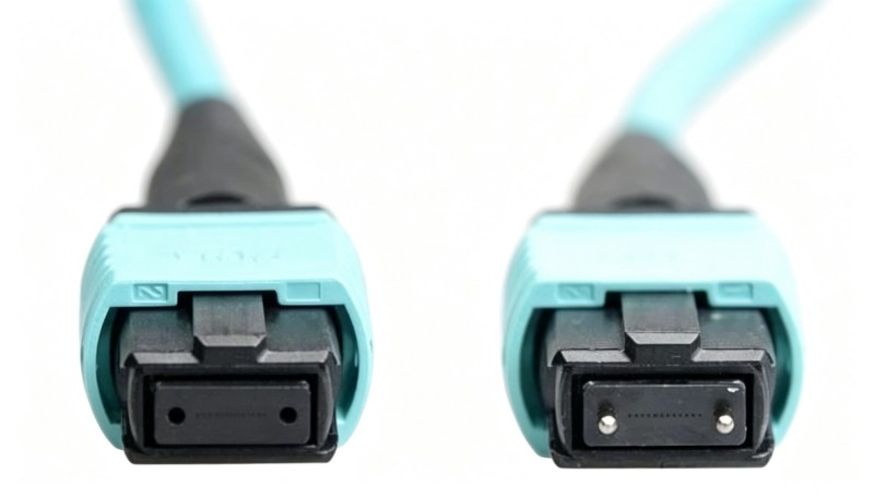
MPO stands for Multi-Fiber Push-On. “Multi-fiber” describes the array of fibers held in one ferrule, while “push-on” refers to the push-pull mating mechanism.
MPO is a standardized connector family rather than one single cable design. The interface dimensions for one-row and two-row MPO variants are defined within the IEC 61754-7 series. This standardization helps compliant connectors and adapters from different manufacturers intermate, although optical performance still depends on ferrule quality, end-face geometry, termination workmanship, cleanliness, and the grades of both mating connectors.
The terms below should not be treated as interchangeable:
MPO connector: The multi-fiber plug at the end of a cable assembly.
MPO adapter: A passive alignment component used to couple two compatible MPO connectors. It does not change fiber routing by itself.
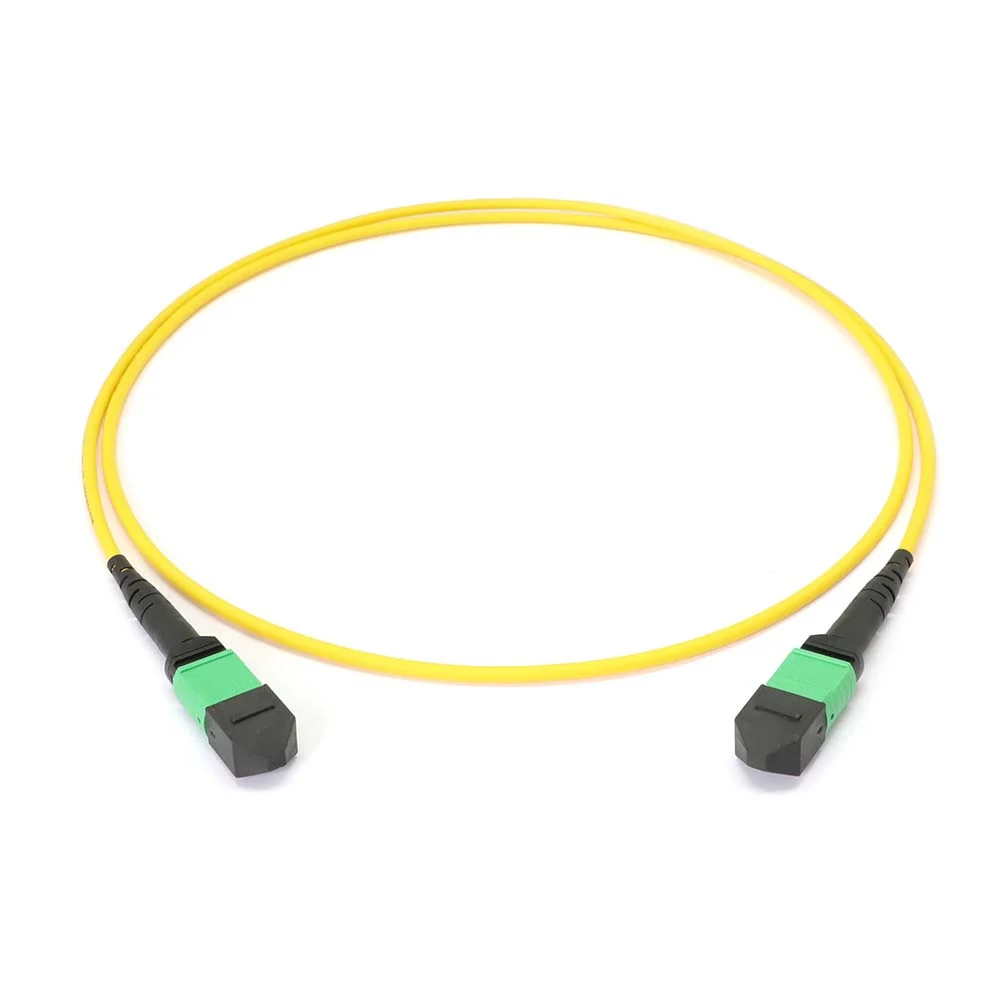
MPO cable assembly: A finished cable with MPO connectors on one or both ends.
MPO cassette: A module that commonly converts an MPO trunk into multiple duplex LC ports.
MPO breakout cable: A cable that transitions from one MPO interface to multiple lower-fiber-count connectors, such as LC duplex connectors.
How Does an MPO Connector Work?
The core of an MPO connector is an MT (mechanical transfer) ferrule. The ferrule contains a precisely positioned array of fiber holes. When two compatible connectors are mated, guide pins on the pinned connector enter the guide holes on the unpinned connector, aligning the corresponding fibers.
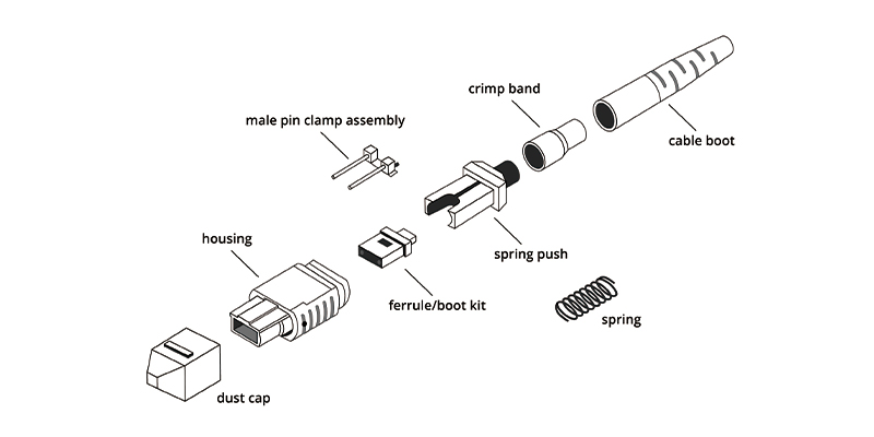
Several parts work together:
MT ferrule: Holds the fibers in one or more rows.
Guide pins or guide holes: Provide mechanical alignment between two ferrules.
Key: Controls connector orientation and helps define the fiber-position mapping.
Position 1 mark: Usually a white dot or triangle identifying the first fiber position.
Outer housing: Provides the push-pull engagement and release mechanism.
Spring: Maintains mating force so the polished fiber end faces remain in physical contact.
Boot and strain relief: Protect the transition from connector to cable.
MPO performance depends on much more than whether the connector clicks into place. Fiber height, adjacent-fiber height differences, ferrule angle, guide-pin alignment, contamination, and scratches can all affect insertion loss or return loss. Because a single ferrule contains many fibers, one damaged or contaminated area may affect one lane while the remaining lanes continue to operate.
MPO Connector Types by Fiber Count
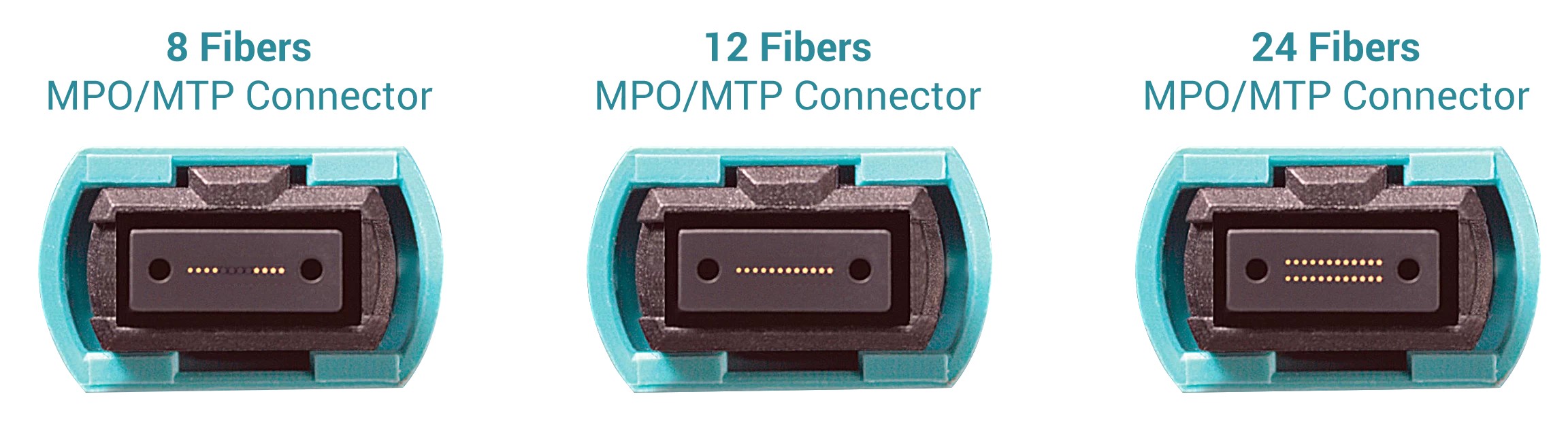
Common MPO configurations include 8, 12, 16, and 24 fibers. Higher counts are also available for specialized high-density applications. The correct count is determined by the cabling architecture and the optical interface—not simply by choosing the highest number.
Configuration | Typical arrangement | Common uses | Important consideration |
|---|---|---|---|
MPO-8 | 8 active positions in one row | Four-lane transmit and four-lane receive parallel optics; Base-8 cabling | Uses all eight fibers in an SR4- or DR4-type parallel link when supported by the transceiver |
MPO-12 | 12 fibers in one row | Structured cabling trunks, cassettes, legacy Base-12 systems, and some parallel links | An eight-fiber parallel application may leave four positions unused |
MPO-16 | 16 fibers in one row | Eight-lane transmit/eight-lane receive applications such as certain SR8 links | Uses an offset keying interface and is not interchangeable with a conventional centered-key MPO-12 interface |
MPO-24 | Two rows of 12 fibers | High-density backbone cabling and aggregation | Requires careful polarity and port-mapping planning |
MPO-8
MPO-8 is commonly associated with four transmit and four receive fibers. It can provide efficient fiber utilization for optical interfaces designed around four parallel lanes in each direction. In practice, an “MPO-8” assembly may use an MPO ferrule format with only eight fiber positions populated, so buyers should verify the connector interface and fiber-position map rather than relying only on the product name.
MPO-12
MPO-12 is widely deployed in pre-terminated backbone systems. It works well for high-density trunks and can be converted to six duplex LC connections through a cassette or breakout assembly. It has also been widely used for parallel optics requiring eight active fibers, with the four center positions left unused in common implementations.
MPO-16
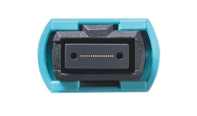
MPO-16 provides 16 fibers in one row and supports optical applications requiring eight transmit and eight receive lanes. Its offset key helps prevent accidental mating with conventional centered-key MPO interfaces. An MPO-16 cable, adapter, and equipment port must therefore be selected as a compatible system.
MPO-24
MPO-24 places 24 fibers in two rows of 12. It can reduce the number of trunk cables in high-density installations, but its polarity, breakout arrangement, installation loss, and bend management require more planning. Higher density is not automatically better when the connected equipment uses fewer active lanes.
MPO Male vs. Female: What Is the Difference?
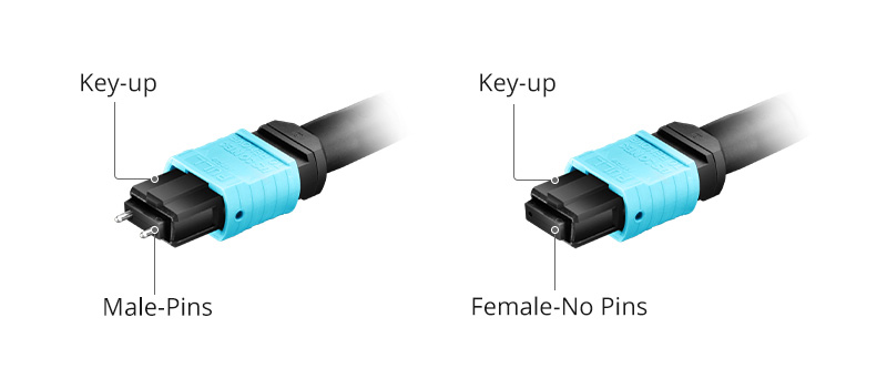
MPO gender refers to the guide pins—not to the outer housing.
A male or pinned MPO connector has two metal guide pins protruding from its ferrule.
A female or unpinned MPO connector has two guide holes and no protruding pins.
A mated connector pair needs one pinned side and one unpinned side so the ferrules align correctly. Two pinned connectors can cause pin collision and damage. Two unpinned connectors lack the guide pins needed for precision alignment.
Active equipment commonly presents a pinned MPO interface, which means a cable connected directly to that equipment normally needs an unpinned connector. Nevertheless, the equipment documentation and actual port should always be checked before ordering; the word “transceiver” or “patch panel” alone is not a complete gender specification.
An MPO adapter does not have male or female fiber contacts in the same sense as the connectors. It aligns the connector housings, while the pins must be supplied by the correct connector in the mated pair.
MPO UPC vs. APC
MPO connectors are available with different end-face polish styles.
MPO UPC
UPC (Ultra Physical Contact) MPO connectors are commonly used with multimode fiber such as OM3, OM4, and OM5. The end face is polished for physical contact without an angled interface. UPC is widely used in short-reach parallel-optics systems.
MPO APC
APC (Angled Physical Contact) MPO connectors use an angled end face to direct reflected light away from the fiber core. APC is commonly associated with single-mode MPO assemblies where return-loss performance is important.
UPC and APC MPO interfaces must not be mated together. Their end-face geometries do not match, which can produce excessive loss and potentially damage the ferrules. Housing color may help with identification, but the product specification and end-face orientation should be treated as authoritative.
Single-Mode vs. Multimode MPO
The fiber type must match the optical transceivers and the link design.
Fiber type | Category | Typical MPO polish | General use |
OS2 | Single-mode | APC is common; confirm the interface | Longer-reach links and single-mode parallel optics |
OM3 | Multimode | UPC | Short-reach data center links and established 40G/100G systems |
OM4 | Multimode | UPC | Higher-bandwidth short-reach data center links |
OM5 | Wideband multimode | UPC | Applications designed for wideband multimode operation |
The achievable distance is defined by the complete optical standard, transceiver, wavelength, fiber grade, connector loss, splices, and other channel components. “OM4 supports 400G” or “OS2 is for 800G” is not sufficiently precise without naming the optical interface and permitted reach.
MPO vs. MTP: Are They the Same?
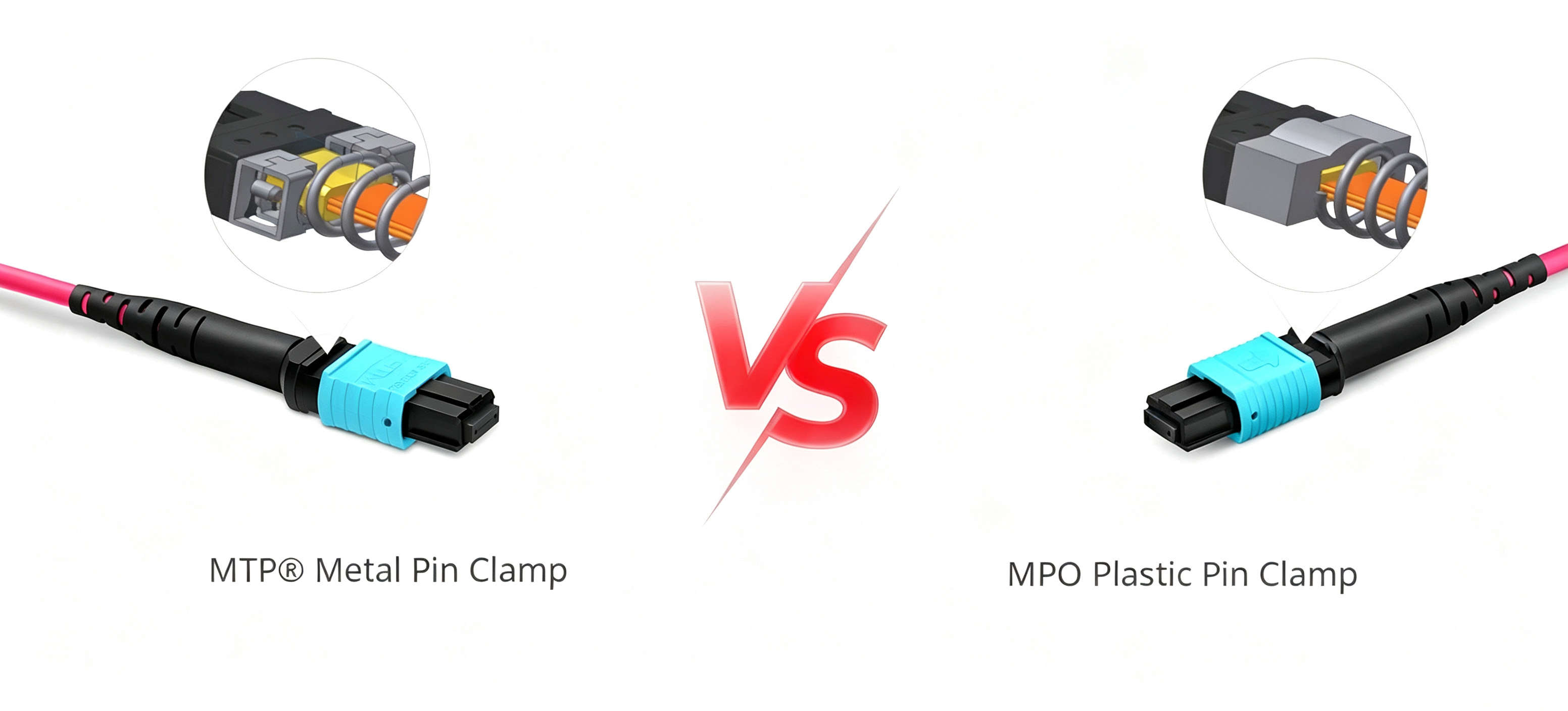
MPO is the generic standardized connector interface. MTP® is a registered trademark of US Conec for its proprietary MPO connector design. In other words, an MTP connector is an MPO-format connector, but not every MPO connector is an MTP connector.
US Conec identifies features such as a removable housing, floating ferrule, and engineered guide-pin design among the characteristics of its MTP platform. These features can improve serviceability, configurability, and mechanical performance. However, buyers should compare actual assembly specifications rather than assume that every product carrying a broad connector label has one fixed insertion-loss value.
Question | MPO | MTP® |
What is it? | Generic standardized multi-fiber connector family | US Conec's proprietary MPO connector platform |
Can multiple manufacturers offer it? | Yes | MTP-branded components originate from US Conec |
Is it an MPO-compatible format? | It is the base format | Yes, when the specific interfaces and keying variants are compatible |
Does the name alone define optical loss? | No | No; check ferrule grade and finished assembly specification |
What should a buyer compare? | Fiber count, polish, pins, polarity, keying, IL/RL, test data | The same parameters, plus the required MTP product generation or feature set |
MTP may be preferred when a project specifies the brand, needs its configurable mechanical features, or requires a qualified assembly built around that platform. A properly manufactured standard MPO assembly can also be suitable when it meets the applicable interface, loss budget, environmental, and reliability requirements.
Common MPO Cable Assemblies
MPO-to-MPO trunk cables
MPO trunk cables connect high-density distribution points and are often installed between patch panels or cassettes. They reduce installation time because the fibers are factory terminated and tested.
MPO-to-LC breakout cables
A MPO breakout or harness cable converts one MPO interface into multiple LC connectors. It may be used to connect a parallel-optics port to several lower-speed ports or to distribute trunk fibers without a cassette.
MPO conversion cables
Conversion assemblies remap one fiber-count or lane arrangement into another compatible architecture. For example, a conversion may support migration between Base-12 infrastructure and equipment using eight active fibers. The exact pin map must be specified.
MPO cassettes
MPO cassettes provide protected transitions from MPO trunks to duplex connectors. They simplify patching but add mated connections to the channel, so their insertion loss must be included in the link budget.
Where Are MPO Connectors Used?
MPO connectors are most valuable where fiber density, installation speed, or parallel transmission matters.
Data center backbone cabling
Pre-terminated MPO trunks consolidate many fibers into fewer cables, reducing pathway congestion and installation labor. At the patch panel, cassettes or breakout assemblies can distribute those fibers to duplex equipment connections.
Parallel optical transmission
Parallel optics transmit data over multiple fibers at the same time. Common examples use four or eight lanes in each direction. The required connector and active fiber positions depend on the exact transceiver standard, so speed alone should not be used as the selection rule.
High-density patching
One MPO interface can replace several duplex connectors at a distribution point. This is useful in data centers, telecom rooms, optical switching systems, and other space-constrained environments.
Network migration
Well-planned trunks, cassettes, and conversion assemblies can support migration between equipment generations. Future readiness depends on fiber type, fiber count, loss budget, polarity architecture, and connector keying—not only on installing the cable with the most fibers.
Advantages and Limitations of MPO Connectivity
Advantages
High fiber density in a compact interface
Faster installation with factory-terminated assemblies
Reduced pathway and patch-panel space
Support for both duplex structured cabling and parallel optics
Factory testing and documented fiber mapping
Flexible trunk, cassette, breakout, and conversion designs
Limitations
Gender and polarity errors can prevent a link from operating
Multiple fibers make end-face cleanliness especially important
High-density links may have tight insertion-loss budgets
Different keying variants are not always physically interchangeable
Troubleshooting may require MPO-specific inspection and test equipment
Product names alone do not define the complete fiber map
Frequently Asked Questions
How many fibers can an MPO connector contain?
Common data center configurations include 8, 12, 16, and 24 fibers. Higher fiber counts are also available for specialized applications. Confirm both the number of installed fibers and the positions used by the equipment.
Is MPO the same as MTP?
Not exactly. MPO is the generic standardized connector family. MTP® is US Conec's proprietary MPO connector platform. Compatible variants can intermate, but fiber count, keying, polish, pins, polarity, and performance grade must still match.
Can two female MPO connectors be connected through an adapter?
They may fit into an adapter, but without guide pins the ferrules will not have the intended precision alignment. A proper mating pair requires a pinned side and an unpinned side.
Can MPO UPC connect to MPO APC?
No. UPC and APC end-face geometries should not be intermated.
Is MPO only used for parallel optics?
No. MPO trunks are also widely used as high-density backbone cabling that transitions to duplex LC connections through cassettes or breakout assemblies.
Which MPO connector is used for 400G or 800G?
There is no single answer based only on the data rate. Different 400G and 800G optical interfaces use different lane counts, fiber types, reaches, and connector arrangements. Check the transceiver standard and port specification first.
Conclusion
An MPO connector combines multiple fibers in one compact, precision-aligned interface. Its density and factory-terminated design make it well suited to backbone cabling and parallel optics, but a reliable deployment depends on more than selecting MPO-8, MPO-12, MPO-16, or MPO-24. Fiber type, polish, pin configuration, polarity, keying, and insertion-loss grade must work together as a complete channel.
If you already understand the connector basics and need help specifying a cable, continue with [How to Choose an MPO Cable: Polarity, Gender, Fiber Count, and Performance].
Need help matching an MPO assembly to your transceiver or cabling architecture? Send Firsol your equipment model, port type, link diagram, fiber type, and required length. Our team can help verify the fiber count, pin configuration, polarity, polish, and loss grade before production.