What Is an E2000 Connector? Features, UPC vs APC, and Selection Guide
An E2000 connector is a fiber optic connector recognized for its push-pull locking mechanism and integrated protective shutter. It provides a detachable optical connection while helping protect the fiber end face when disconnected.
Choosing the right E2000 connector requires more than matching the connector shape. Fiber type, end-face polish, boot size, and assembly requirements all affect which version you need.
This guide explains how E2000 fiber connectors work, compares UPC and APC options, and outlines how to select connector components for custom pigtails and patch cords.
What Is an E2000 Fiber Connector?
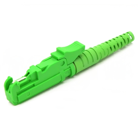
An E2000 connector, also commonly written as E-2000, terminates an optical fiber so it can be connected to another compatible fiber interface through an adapter.
One of its distinguishing features is a spring-loaded protective shutter. When the connector is disconnected, the shutter covers the ferrule end face. During insertion into a compatible adapter, the shutter opens to allow the connection to be made.
E2000 connectors are available for single mode and multimode fiber applications. The connector interface, fiber category, and polishing style must all match the requirements of the intended connection.
A simplex E2000 connector terminates one fiber. Applications using separate transmit and receive fibers require an appropriate arrangement of two fiber paths.
How Does an E2000 Connector Work?
An E2000 connection combines end-face protection, optical alignment, and mechanical retention.
The terminated fiber is held within a precision ferrule. When two compatible connectors are inserted into an adapter, an alignment sleeve positions their ferrules so the fiber ends can form an optical connection. The locking mechanism helps maintain the connection during normal handling.
The main elements have different functions:
Element | Function |
|---|---|
Connector housing | Supports the connector structure and handling mechanism |
Protective shutter | Helps shield the disconnected ferrule end face |
Ferrule | Holds and positions the terminated fiber |
Adapter alignment sleeve | Aligns the mating ferrules |
Locking mechanism | Helps prevent unintended disconnection |
Boot | Supports the fiber or cable at the connector entry point |
These mechanical features support a reliable connection, but optical performance also depends on termination quality, end-face geometry, cleanliness, and the condition of the mating components.
A connector may latch correctly and still exhibit excessive loss if its end face is contaminated or improperly finished.
Does the Shutter Eliminate Cleaning?
No. The shutter helps protect the end face, but it does not make the connector immune to contamination.
Inspect the connection using appropriate equipment and follow suitable cleaning procedures when necessary. Use tools compatible with the connector’s shuttered design, and never look into a potentially active optical interface.
E2000 UPC vs E2000 APC: What Is the Difference?
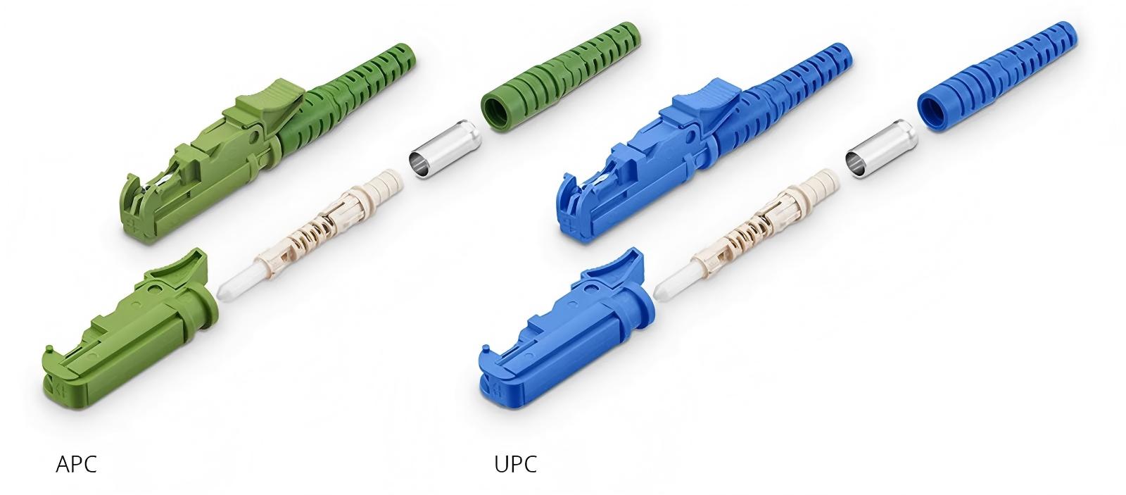
UPC and APC describe different fiber end-face polishing geometries. The correct choice depends on the mating interface and the system’s back-reflection requirements.
E2000/UPC Connectors
UPC stands for Ultra Physical Contact. A UPC termination has a polished, curved end face without the intentional angle used in APC geometry.
Choose E2000/UPC when the intended mating connection specifies UPC. In the FIRSOL component range covered here, UPC options are available for OS2 single mode fiber and OM1, OM2, OM3, and OM4 multimode fiber.
E2000/APC Connectors
APC stands for Angled Physical Contact. The angled end face helps direct reflected light away from the guided path back toward the optical source.
This geometry generally provides lower back reflection than a comparable UPC connection, making APC relevant when the system has stricter reflection requirements.
An APC connector should be selected to match the specified interface. It is not a universal replacement for UPC.
Selection factor | E2000/UPC | E2000/APC |
|---|---|---|
End-face geometry | Non-angled physical-contact polish | Angled physical-contact polish |
Reflection consideration | Used where UPC performance is specified | Used where lower back reflection is required |
Direct mating requirement | Compatible UPC interface | Compatible APC interface |
FIRSOL fiber options covered here | OS2 and OM1–OM4 | OS2 |
Main purchasing check | Confirm fiber type and UPC requirement | Confirm fiber type and APC requirement |
Can E2000 UPC and APC Connectors Be Mated?
Do not directly mate UPC and APC end faces. Their different geometries can cause poor optical performance and may damage the end faces.
An adapter aligns compatible connectors; it does not convert UPC geometry into APC geometry.
A finished cable can have UPC at one end and APC at the other when each end connects to its matching interface. This is different from directly mating a UPC connector with an APC connector at the same connection.
Insertion Loss and Return Loss
Insertion loss and return loss describe different aspects of connector performance:
Insertion loss measures the reduction in optical power through a connection. Lower values are generally preferable.
Return loss describes the relationship between incident power and reflected power. Higher positive values indicate less reflection.
Reflectance expresses the reflected-to-incident power relationship using negative values. More negative values indicate less reflection.
The APC or UPC designation alone does not establish a guaranteed performance value. Check the specifications and test conditions for the completed assembly.
Single Mode and Multimode E2000 Connectors
“E2000” identifies the connector interface. OS2 and OM1–OM4 identify the fiber category used in the assembly.
Selecting the right component therefore requires checking both the connector configuration and the fiber being terminated.
Fiber category | Fiber description | FIRSOL termination options |
|---|---|---|
OS2 | Single mode | E2000/UPC and E2000/APC |
OM1 | 62.5/125μm multimode | E2000/UPC |
OM2 | 50/125μm multimode | E2000/UPC |
OM3 | 50/125μm multimode | E2000/UPC |
OM4 | 50/125μm multimode | E2000/UPC |
For replacement or maintenance work, confirm the existing cable specification rather than relying only on jacket or connector color.
A connector component does not change the optical category of the fiber. For example, installing a component labeled for an OM4 assembly does not turn OM3 fiber into OM4.
The completed link’s capabilities depend on the actual fiber, optical equipment, operating wavelength, distance, and connection quality.
Choosing the Right Boot Size
The boot supports the fiber or cable where it enters the connector and helps reduce stress at that transition.
Its size refers to the buffered fiber or cable it is designed to accommodate. It does not refer to the fiber core diameter.
FIRSOL E2000 connector components are available with 0.9mm, 2.0mm, and 3.0mm boot options.
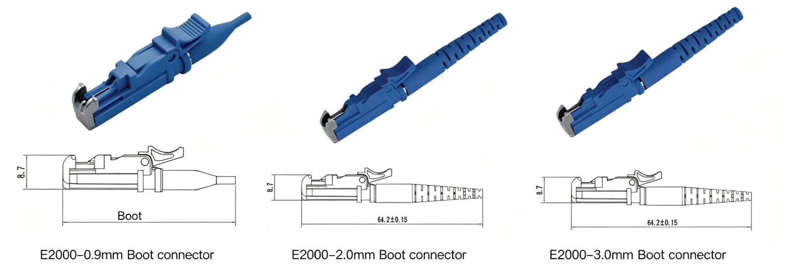
Boot size | Intended fit | Typical assembly use |
|---|---|---|
0.9mm | 900μm buffered fiber | Custom pigtails and internal fiber terminations |
2.0mm | Cable with a 2.0mm outer diameter | Custom patch cords and cable assemblies |
3.0mm | Cable with a 3.0mm outer diameter | Custom patch cords and cable assemblies |
0.9mm Boots
A 0.9mm boot is intended for compatible 900μm buffered fiber. This configuration is useful for pigtail production and assemblies where buffered fiber is routed inside an enclosure.
The 900μm dimension describes the buffered fiber, not the bare glass or its core.
2.0mm and 3.0mm Boots
Choose a 2.0mm or 3.0mm boot according to the cable’s outer diameter and the specified assembly hardware.
Neither size inherently provides better optical performance. A correctly matched boot and properly assembled cable retention system are more important than selecting a larger size.
For production work, verify compatibility with the complete component set, including any crimping and strength-member retention parts.
E2000 Connector Components vs Pigtails and Patch Cords
Before ordering, decide whether you need parts for manufacturing or a finished cable assembly.
Connector Components
Connector components are supplied for termination and assembly. The exact included parts should be confirmed against the product listing or assembly drawing.
Producing a finished termination requires an appropriate process for fiber preparation, securing the fiber, polishing, inspection, and optical testing.
These products are suitable for cable assembly manufacturers and other users equipped to perform the required work.
Fiber Pigtails
A fiber pigtail has a connector installed at one end and an unterminated fiber at the other. The unterminated end can be integrated into an installation through an appropriate splicing or termination process.
Pigtails are useful when a connectorized fiber needs to be incorporated into a distribution enclosure or other fiber assembly.
Fiber Patch Cords
A fiber patch cord has connectors installed at both ends. The ends may use the same connector format or different formats to suit the equipment being connected.
A completed and tested patch cord is the relevant choice when the application requires a ready-to-connect cable.
Product | Supplied condition | Typical purpose |
|---|---|---|
Connector components | Parts requiring fiber termination and assembly | Manufacture custom terminations |
Fiber pigtail | Connector installed at one end | Integrate a terminated fiber into an installation |
Patch cord | Connectors installed at both ends | Connect compatible optical ports |
Ordering components when a finished cable is needed can add unexpected manufacturing work. Confirm the supplied condition before comparing prices.
E2000 vs SC vs LC Connectors
E2000, SC, and LC are different connector interfaces. The first selection criterion is the interface required by the equipment or patch panel.
E2000’s integrated protective shutter is a characteristic feature. SC uses a familiar push-pull format, while LC provides a compact interface often selected where connection density matters.
However, connector family alone does not determine the best solution for every installation.
Consideration | What to check |
|---|---|
Equipment compatibility | The connector format required at each port |
Polish type | Whether each connection requires UPC or APC |
Panel arrangement | Available space and cable-routing requirements |
Maintenance | Compatible inspection and cleaning tools |
Existing infrastructure | Connector formats already used in the installation |
Optical performance | Specifications of the actual completed assemblies |
Do not assume that E2000 automatically has lower insertion loss than every SC or LC product. Compare actual product specifications and test results.
If two devices use different connector formats, a suitable hybrid patch cord may connect them. Each end must match its own port, and the fiber must be appropriate for the optical link.
How to Select E2000 Connector Components
A clear ordering specification reduces the risk of receiving parts that do not suit the intended assembly.
1. Identify the Fiber Category
Specify OS2, OM1, OM2, OM3, or OM4 according to the actual fiber being terminated.
For an existing installation, check the cable documentation or markings before ordering.
2. Confirm UPC or APC
Determine the polish required at the intended connection. Do not select solely by connector color or assume APC can replace UPC.
3. Match the Boot Size
Choose 0.9mm for compatible 900μm buffered fiber, or 2.0mm or 3.0mm to match the cable outer diameter.
Confirm that the remaining termination hardware also supports the cable construction.
4. Check the Supplied Components
Review which parts are included and whether they are compatible with your assembly process and tooling.
For repeat production, use a clearly identified part number and approved assembly specification.
5. Define Finished-Assembly Performance
Specify required insertion loss, return loss, inspection criteria, and test conditions where relevant.
These requirements should be verified on the completed termination. Component selection is only one part of achieving the required result.
A clear purchasing description might be:
OS2 Single Mode Simplex E2000/APC 2.0mm Boot Fiber Connector Components for custom patch cord assembly.
Quantity, required performance, and any additional assembly requirements can then be added.
FIRSOL E2000 Connector Component Options
FIRSOL offers simplex E2000 connector components for custom fiber termination and cable assembly, including:
OS2 single mode E2000/UPC and E2000/APC options.
OM1, OM2, OM3, and OM4 multimode E2000/UPC options.
0.9mm, 2.0mm, and 3.0mm boot configurations.
Browse the FIRSOL E2000 Connector Components range to select the fiber category, polishing style, and boot size required for your assembly.
For quotation requests, include the required configuration, quantity, and any specific performance or supplied-part requirements.
Frequently Asked Questions
Are E2000 and E-2000 Different Connector Types?
These spellings are commonly used for the same connector family. Confirm the actual product specification and part number when purchasing.
Are E2000 Connectors Available for Both Single Mode and Multimode Fiber?
Yes. The FIRSOL range includes OS2 single mode and OM1–OM4 multimode configurations. Select the version intended for the fiber being terminated.
Can I Connect E2000/APC Directly to E2000/UPC?
No. The mating end-face geometries must match. Directly mating APC and UPC can result in poor performance and possible end-face damage.
Does the Protective Shutter Make the Connector Dustproof?
The shutter helps protect the end face but should not be treated as a guarantee against contamination. Inspection and appropriate cleaning remain necessary.
Is a 3.0mm Boot Better Than a 2.0mm Boot?
Neither is inherently better. Choose the size that fits the cable outer diameter and the specified termination hardware.
Does an OM4 Connector Component Upgrade OM3 Fiber?
No. A connector component does not change the optical properties or bandwidth category of the fiber.
Are E2000 Connector Components Ready to Plug Into Equipment?
They require fiber termination, assembly, finishing, and testing before use. Choose an appropriate finished cable assembly if you need a ready-to-connect product.
What Information Should I Include in an Order?
Provide the fiber category, UPC or APC requirement, boot size, quantity, and intended assembly use. Include any optical performance targets, testing requirements, or specific parts that must be supplied.