What Is a Blockless PLC Splitter? Packaging and Selection Guide
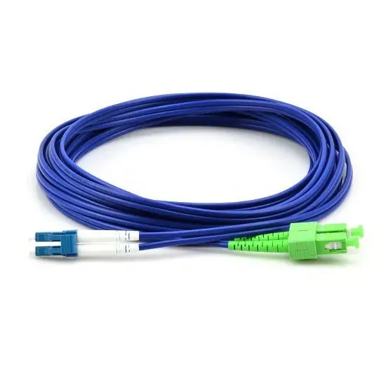
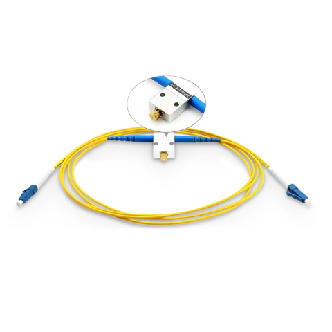
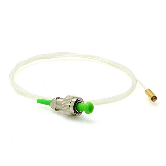
A blockless PLC splitter is a passive optical splitter supplied in a compact module package with protected fiber leads. It is also commonly called a mini module PLC splitter. The format is useful when a splitter must fit into an enclosure that already provides mounting, fiber routing, and environmental protection.
Choosing one involves more than counting output fibers. The module has to fit, the connections must match, and the optical path must remain within the system's operating limits. This guide explains the packaging choices and the information to check before ordering.
What Does “Blockless” Describe?
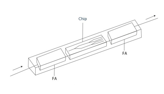
Blockless describes a packaging style within the PLC splitter family. It does not mean that the device has no PLC chip. The optical splitting function still uses planar waveguides; the package determines how the component and its fiber leads are protected and integrated into the installation.
A blockless PLC splitter is also known as a mini module PLC splitter. These names refer to the same packaging type, with terminology varying between manufacturers. For installation, check the dimensions of the selected model and allow sufficient space for pigtail routing and connector access.
How the Splitter Fits into a PON
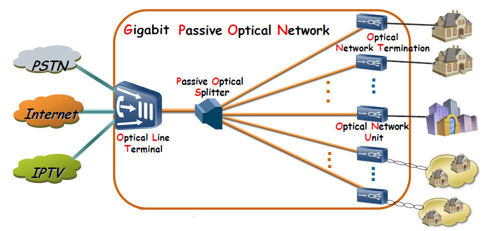
In a passive optical network, a splitter distributes downstream optical signals to multiple branches and provides a shared return path upstream. The OLT and ONTs manage the communication; the passive splitter does not assign bandwidth, decode traffic, or switch between customers. See the Fiber Optic Association's PON reference for the broader architecture.
For a 1×N model, the designation identifies one input and N output fibers. It does not specify the connector polish, package dimensions, or guaranteed reach. Record those separately when preparing a bill of materials.
Blockless vs. Bare Fiber vs. ABS Box
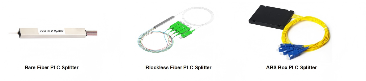
All three options can use PLC splitting technology. Their installation requirements differ because of the housing and the supplied fiber protection.
Package | Selection focus |
|---|---|
Blockless / mini module | Compact integration with space for protected pigtails and service access |
Bare fiber | Handling and protection of the supplied fiber leads within the host assembly |
ABS box | The box dimensions, mounting method, and routing of the exiting pigtails |
A bare fiber splitter may be appropriate where the host assembly manages the fibers and splice protection. A blockless module is worth evaluating when protected leads are useful but the available space is limited. An ABS box splitter is another option when its housing and mounting arrangement suit the installation.
The package label alone does not establish lower insertion loss, better reliability, or outdoor suitability. Compare the specifications and qualification evidence of the actual devices.
Choose the Output Count and Check the Optical Budget
Start with the required branches at the distribution point. Then check the optical loss through the whole route. A higher output count divides the available optical power among more branches, so it changes the loss budget even if the package still fits.
A practical path calculation includes the splitter or splitters on that route, fiber attenuation at the relevant wavelengths, splice loss, connector-pair loss, any other passive components, and an engineering margin. Use the equipment supplier's limits for the actual OLT and ONT combination, including any minimum attenuation requirement.
As a mathematical illustration, an ideal equal 1×N division produces a per-branch splitting loss of 10 log10(N) dB. Ideal 1×8 and 1×32 values are approximately 9.03 dB and 15.05 dB. These are calculated ideal values, not product specifications. Real assemblies introduce additional loss, and the specified maximum must be used for procurement and design.
If a connection is already included between the measurement reference planes of an assembly specification, do not add the same loss a second time. Conversely, include connection points that lie outside those reference planes. Confirm this boundary before using a catalog value in the network budget.
Compare One Stage with a Cascaded Arrangement
A single 1×32 stage and a fully populated 1×4 followed by four 1×8 devices both provide thirty-two final branches. Their locations and installation needs differ. For a selected path in the cascaded arrangement, light passes through one 1×4 and one 1×8 device, so both stage losses belong in that path's calculation.
For illustration, Firsol currently lists maximum insertion-loss values of 7.4 dB for its 1×4 blockless model and 10.7 dB for its 1×8 blockless model. Their arithmetic sum is 18.1 dB. Its 1×32 blockless model is listed at 16.9 dB.
That arithmetic is a preliminary comparison of published limits, not a measured network result. Confirm consistent test conditions and connector treatment, then include the remaining route losses. The stage arrangement also affects where fibers are routed and where technicians need access.
Specify Connections and Pigtails
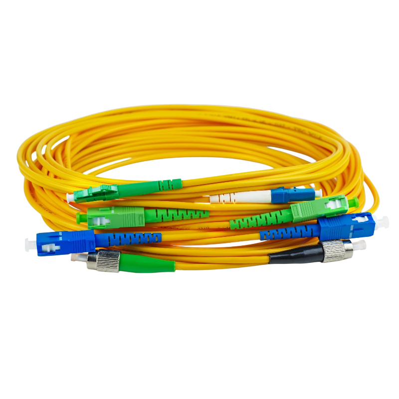
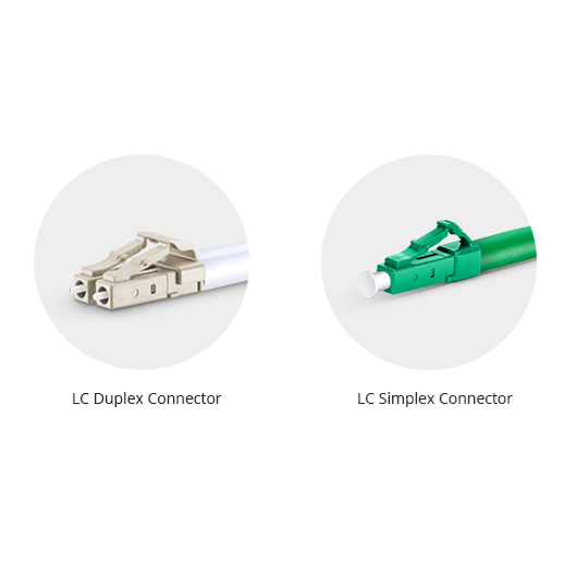
Give the input and output connector requirements separately. For example, an enclosure may need an SC/APC input while the outputs are supplied without connectors for splicing. Confirm that this configuration is supported by the selected product and appropriate for the mating equipment.
Order enough pigtail length for the intended routing, splice arrangement, and service access. The module body's dimensions do not include the space needed to route all the leads. More output fibers require more management space even when the body remains relatively small.
The Firsol models discussed here offer 900 µm pigtails and separate input/output connector selections. Review the product configuration fields before ordering, and include any special length or labeling requirements in your inquiry.
Check Mechanical Fit and Environmental Requirements
Use the actual enclosure drawing to identify a mounting position. Check whether the closure or cover can shut without pressing on the leads, whether connector ends remain accessible, and whether the routing respects the required bend limits. Inspect the complete assembly, not just the rectangular space occupied by the module.
For outdoor use, assess the host enclosure's protection against the site's exposure conditions and verify that every component operates within its environmental limits.
What About 2×N Models?
A 2×N splitter has two input ports and N output ports. Select it when the network architecture requires that port arrangement, and use the specifications for the 2×N device rather than substituting values from a 1×N model.
The presence of two inputs does not make the splitter an automatic failover controller. Any protection arrangement depends on the rest of the system, including compatible equipment and its configuration.
Prepare an Order That Can Be Checked
An example specification might read: “1×8 blockless PLC splitter; G.657.A1 single mode fiber; 900 µm pigtails; 1.0 m length; SC/APC input; SC/APC outputs; quantity 20.” This is an illustrative configuration, not a recommendation for every network.
Attach the available mounting dimensions if fit is critical. Identify the operating wavelengths and any required test documentation, and ask the supplier to confirm the insertion-loss reference planes for the selected assembly. This gives both purchasing and engineering a configuration they can verify.
Browse Firsol blockless PLC splitters to compare available configurations. For additional background, read our PLC splitter overview and PLC vs. FBT comparison.