PLC vs FBT Splitter: Which One Should You Choose
When you need to divide an optical signal across multiple fibers, you have two mainstream choices: FBT (Fused Biconical Taper) splitters and PLC (Planar Lightwave Circuit) splitters. Both are passive and both work — but they behave very differently in wavelength stability, port uniformity, and scale. This guide compares them side by side so you can pick the right technology for your network.
What Is an FBT Splitter?
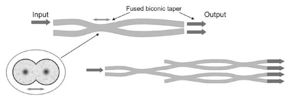
An FBT splitter is made by twisting two or more fibers together, heating them, and stretching (fusing) them into a biconical taper. Where the cores touch, evanescent coupling transfers a portion of the light from one fiber to the other. By controlling the taper length, the manufacturer sets the split ratio (50/50, 30/70, 10/90, etc.).
FBT technology is mature, low-cost, and flexible for uneven (asymmetric) split ratios, which makes it useful for tap couplers and monitor ports. Its downside is that the coupling is wavelength-dependent, so performance changes across 1310, 1490 and 1550 nm.
What Is a PLC Splitter?
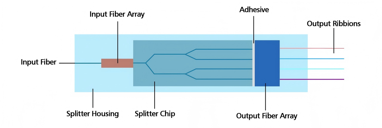
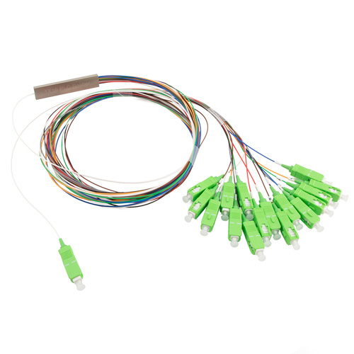
A PLC splitter uses a silica-on-silicon waveguide chip with a photolithographically defined tree of Y-branches. Because the geometry is fixed, splitting is uniform across all output ports and stable across the full 1260–1650 nm window. This makes PLC the natural fit for GPON, XG(S)-PON and any WDM overlay. For deeper background, see our PLC splitter guide.
PLC vs FBT Splitter: Side-by-Side Comparison
Feature | PLC Splitter | FBT Splitter |
|---|---|---|
Technology | Planar waveguide chip | Fused biconical taper |
Operating wavelength | 1260 – 1650 nm (flat) | Best at 1310 / 1490 / 1550 nm |
Split ratios | Equal only (1×2 to 1×64+) | Equal or unequal (e.g. 10/90, 30/70) |
Output uniformity | Excellent (≤ 1.5 dB) | Poor at high split counts |
Max practical split | 1×64 (single chip) | ~1×32 (cascaded) |
Temperature stability | -40 to +85 °C, low drift | -5 to +75 °C typical |
Failure rate | Very low | Higher due to fused joints |
Cost (1×2, 1×4) | Higher | Lower |
Cost per port at 1×32/1×64 | Lower | Higher |
When to Choose FBT
Low split counts (1×2, 1×4) where cost is the driver.
Applications needing unequal ratios such as tap couplers, monitoring, or OTDR test points.
Single-wavelength systems (1310 or 1550 nm) where wavelength flatness doesn’t matter.
When to Choose PLC
GPON, XG-PON, XGS-PON and any FTTH access network.
Networks carrying multiple wavelengths (1310 + 1490 + 1550 + 1577 nm).
High split counts (1×16, 1×32, 1×64) where uniformity is critical.
Outdoor and temperature-cycling deployments.
Practical Recommendation
For almost every modern access network, PLC is the default choice. Its wavelength flatness and uniformity are essential for PON overlays and future WDM upgrades. Keep FBT in the toolbox for tap couplers, monitor ports, and cost-sensitive 1×2 / 1×4 splits in legacy single-wavelength systems.
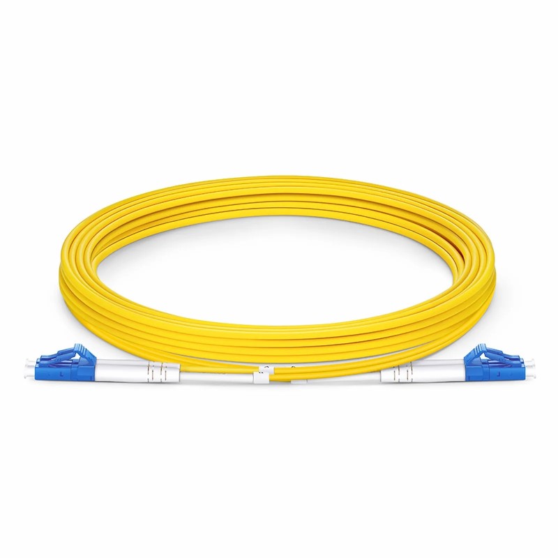
Either way, protect your loss budget with quality patch cables and choose G.657.A1/A2 fiber for tight bends inside enclosures.
Frequently Asked Questions
Are PLC and FBT splitters interoperable in the same network?
Yes. Both are passive, single mode devices with standard connectors, so you can mix them — but keep the wavelength-sensitive FBT parts on single-wavelength segments only.
Which has lower insertion loss?
At small ratios (1×2, 1×4) losses are similar. At 1×16 and above, PLC delivers noticeably lower and more uniform loss.
Can FBT handle 1×64 splitting?
Only by cascading multiple stages, which stacks loss and uniformity errors. For 1×32 or higher, PLC is strongly preferred.
Which is more reliable outdoors?
PLC. Its wider operating temperature range and solid-state waveguide construction handle outdoor cabinets and aerial closures better than fused fiber joints.
Not sure which technology fits your project? Talk to Firsol’s engineers — we’ll size and specify the right splitter for your loss budget.