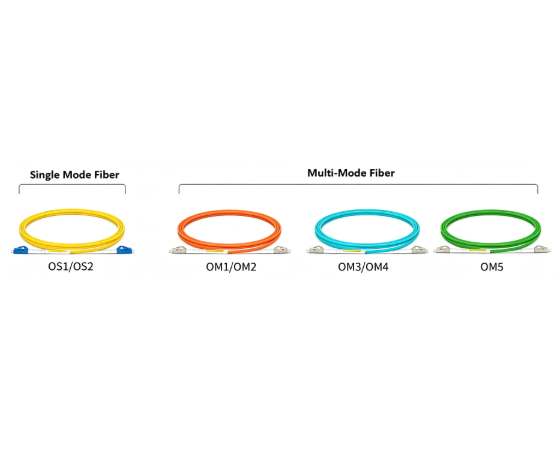
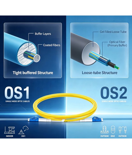
PLC Splitter Explained: Types, Split Ratios & How to Choose
A PLC (Planar Lightwave Circuit) splitter is a passive optical device that divides a single input fiber into multiple output fibers with a uniform split ratio across a wide wavelength range. It is the workhorse behind almost every modern PON/FTTH network. This guide explains how PLC splitters work, the split ratios and package types available, and how to choose the right one for your project.
What Is a PLC Splitter?
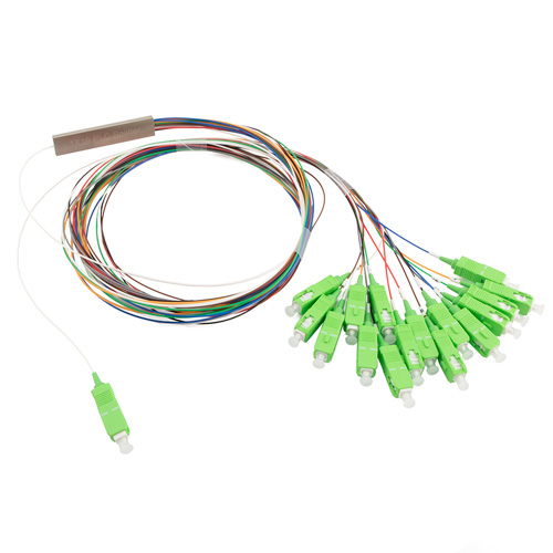
A PLC splitter uses a silica-on-silicon planar waveguide chip to split light. Waveguide branches are photolithographically defined on the chip so that input power is divided evenly among all outputs. Because the split is defined by geometry rather than by a fused fiber taper, PLC splitters offer equal loss across all ports and stable performance from 1260 nm to 1650 nm — covering O, E, S, C and L bands used by GPON, XG(S)-PON and 10G/25G/50G-PON.
How a PLC Splitter Works
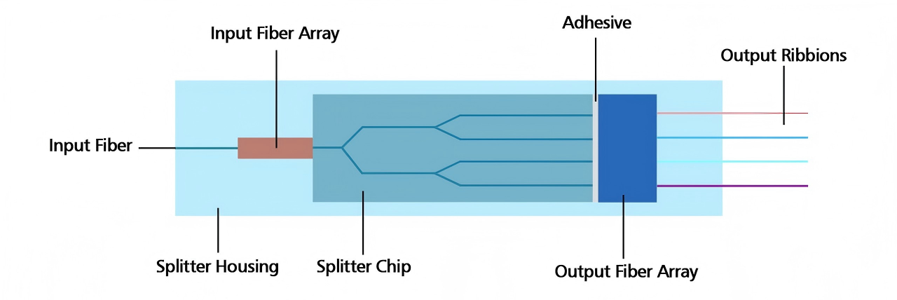
A typical PLC splitter has three parts:
Input pigtail aligned to the PLC chip input waveguide.
PLC chip with a tree of Y-branch waveguides that split the light in successive 1×2 stages.
Output pigtail array aligned to the chip outputs, terminated in bare fiber, 900 µm tubing, or connectors.
Because the splitting is symmetric and wavelength-flat, one 1×32 PLC splitter can serve 32 subscribers on a shared OLT port with predictable loss.
Common PLC Splitter Types by Split Ratio
PLC splitters are available in 1×N (one input) and 2×N (two inputs, used for redundancy / protection) configurations.
Split Ratio | Typical Insertion Loss (dB) | Typical Application |
|---|---|---|
1×2 | ≤ 3.6 | Cascaded / drop splitting |
1×4 | ≤ 7.2 | Small MDU, cascaded stages |
1×8 | ≤ 10.5 | FTTH access, small PON |
1×16 | ≤ 13.8 | Standard FTTH distribution |
1×32 | ≤ 17.1 | GPON access, most common ratio |
1×64 | ≤ 20.5 | XG(S)-PON high-density access |
2×32 | ≤ 17.5 | Protected PON with dual feeders |
These are indicative values; check the datasheet for the exact grade you purchase.
PLC Splitter Package Types
The same PLC chip can be packaged for very different install environments:
Bare fiber plc splitter — smallest form factor, spliced directly inside closures or trays.
Blockless plc splitter — 900 µm tubing on both ends, protected by a stainless-steel sleeve. Used inside splice trays.
ABS box plc splitter — plastic housing with pigtails or connectors, ideal for wall boxes and terminal boxes.
LGX cassette plc splitter — standard LGX footprint for rack mount patch panels and distribution frames.
1U rack-mount plc splitter — connectorized module for central office / data center racks.
Key Optical Specifications
Parameter | Typical Value |
|---|---|
Operating wavelength | 1260 – 1650 nm |
Uniformity (loss between ports) | ≤ 0.6 – 1.5 dB |
Return loss (UPC / APC) | ≥ 50 dB / ≥ 55 dB |
Polarization dependent loss (PDL) | ≤ 0.3 dB |
Directivity | ≥ 55 dB |
Operating temperature | -40 °C to +85 °C |
PLC Splitters in FTTH / PON Networks
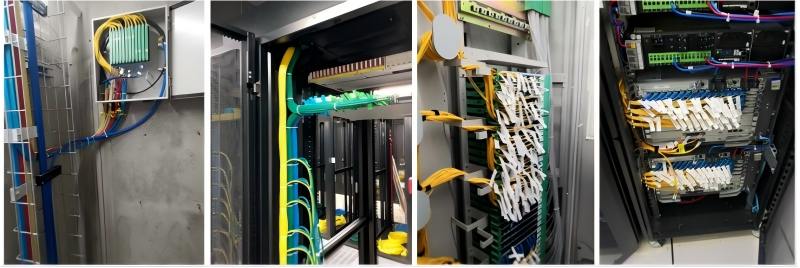
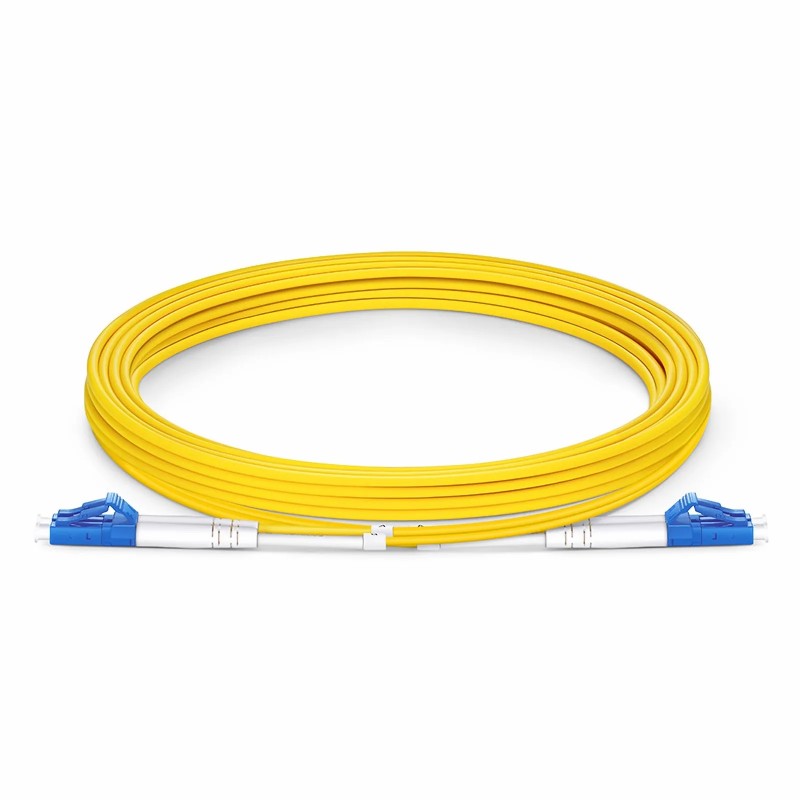
In a standard GPON, the OLT feeds an outside-plant PLC splitter (typically 1×8 or 1×16), then a second-stage splitter at the terminal box (1×4 or 1×8), reaching an aggregate 1:32 or 1:64 subscribers. For XG(S)-PON, operators often deploy a single 1×64 stage. Because the loss budget is tight, use APC connectors to keep return loss high and combine PLC splitters with quality fiber patch cables and single mode optical fiber throughout the plant.
How to Choose the Right PLC Splitter
Split ratio — match your subscriber count and PON loss budget (typically 28 dB for GPON Class B+).
Package type — blockless for splice trays, ABS/LGX for boxes and racks.
Connector — SC/APC is the FTTH default; use LC/APC for high-density panels.
Fiber type — G.657.A1 or A2 pigtails handle tight bends in enclosures. See our G.652 vs G.657 guide.
Environment — verify operating temperature and IP rating for outdoor deployments.
Frequently Asked Questions
What is the difference between PLC and FBT splitters?
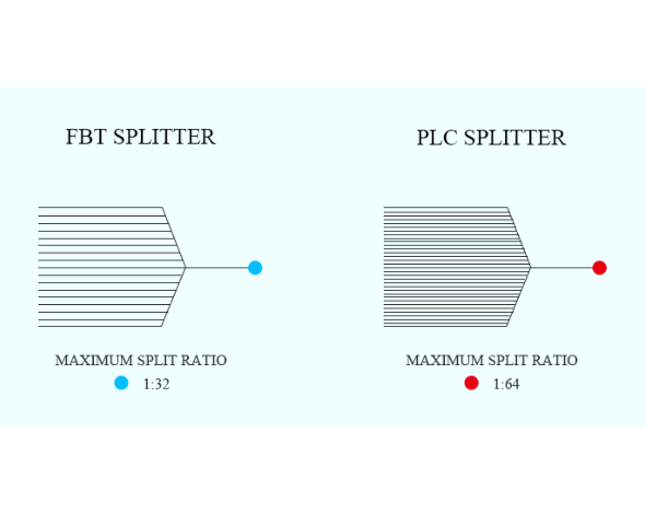
PLC splitters use a planar waveguide chip and offer equal loss and stable performance across a wide wavelength range. FBT splitters fuse fibers together and are cheaper but wavelength-sensitive. See our full PLC vs FBT comparison.
What is a 2×N PLC splitter used for?
Two inputs allow dual-feeder / protection PON architectures — if one OLT feeder fails, service continues on the second input.
Is a 1×32 splitter always the right choice for GPON?
1×32 is the most common ratio, but 1×64 (XG(S)-PON) or cascaded 1×4 + 1×8 designs may fit your loss budget better. Always calculate end-to-end loss including connectors, splices and fiber attenuation.
Do PLC splitters work with both single mode and multimode fiber?
Standard PLC splitters are designed for single mode fiber. Multimode splitting typically uses FBT or fiber couplers.
Need help sizing a splitter for your PON? Contact Firsol and our engineers will size the splitter and matching connectivity for your project.