In-Line Variable Optical Attenuators: How VOAs Control Optical Power in Fiber Networks
In a fiber optic system, excessive optical power can be just as problematic as insufficient power. A receiver operating above its recommended input range may become saturated, while a weak signal can reduce system margin and increase the risk of transmission errors.
An in-line variable optical attenuator, commonly called an in-line VOA, provides a controlled and adjustable method of reducing optical power without disconnecting or redesigning the optical link. It is widely used in fiber optic testing, optical communication systems, amplifier setups, laboratory experiments, and equipment manufacturing.
This article explains how an in-line VOA works, where it is used, which specifications matter, and how to select an appropriate configuration.
What Is an In-Line Variable Optical Attenuator?
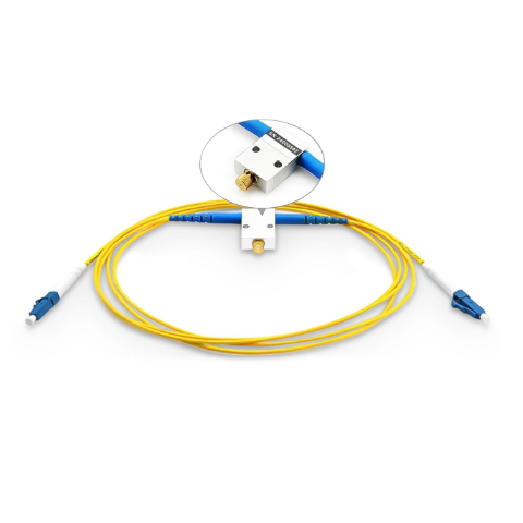
An in-line variable optical attenuator is an optical power-control device installed directly in a fiber optic transmission path. Its purpose is to introduce a controlled amount of attenuation so that the optical power reaching a receiver, amplifier, detector, or test instrument remains within the required range.
Unlike a fixed optical attenuator, which provides a predetermined attenuation value, a VOA allows the attenuation level to be adjusted. Depending on the design, adjustment may be performed:
Manually through a mechanical control;
Electrically through an external control signal;
Automatically as part of an optical power-management system.
Manual in-line VOAs are particularly useful in laboratories, production test stations, equipment installation, troubleshooting, and applications where engineers need direct and repeatable control of optical power.
How Does an In-Line VOA Work?
A VOA reduces the amount of optical power transmitted through the device while maintaining the continuity of the optical path.
Different VOA technologies use different attenuation mechanisms. Common approaches include:
Mechanical attenuation
A mechanical VOA changes the coupling condition of the optical path. Depending on its internal construction, attenuation may be adjusted by changing the alignment, spacing, angle, or obstruction between optical elements.
This approach is commonly used in compact manual in-line VOAs because it does not require an electronic controller and allows straightforward adjustment by the operator.
MEMS-based attenuation
Micro-electromechanical systems, or MEMS, use microscopic movable mirrors or structures to control the amount of light coupled into the output path. MEMS technology is often used in electronically controlled VOAs and multi-channel optical power-management systems.
Electro-optic attenuation
Electro-optic designs use an applied electrical signal to change the optical properties of a material or device. These VOAs can provide rapid and automated power adjustment, although they normally require a driver or control circuit.
Firsol in-line VOAs use a mechanically adjustable structure intended for applications requiring compact construction, stable attenuation control, and convenient integration into fiber optic test or transmission links.
Why Is Optical Power Control Important?
Optical components are designed to operate within specified input-power ranges. When the power level falls outside those ranges, system performance may become unstable or measurement results may become unreliable.
An in-line VOA helps engineers control several common conditions.
Preventing receiver saturation
Optical receivers and test instruments have maximum input-power limits. A VOA can reduce excessive power before the signal reaches the receiving device, helping keep the receiver within its recommended operating range.
A VOA should not, however, be treated as a substitute for proper laser-safety practices or dedicated protection equipment.
Simulating transmission loss
During product development and qualification, engineers frequently need to reproduce the loss that would occur in a real fiber link. An adjustable VOA makes it possible to simulate different link lengths, connector losses, splitter losses, or network conditions without physically rebuilding the test setup.
For example, an engineer can gradually increase attenuation while monitoring receiver sensitivity, optical signal-to-noise ratio, or bit error rate.
Setting amplifier input and output power
VOAs can be installed before or after an EDFA or another optical amplifier to adjust the amplifier input level, control the delivered output power, or evaluate system behavior under different optical loading conditions.
The VOA does not necessarily control the amplifier gain directly. Instead, it controls the optical power entering or leaving the amplifier and therefore influences the amplifier’s operating condition.
Managing power in WDM systems
In wavelength-division multiplexing systems, a broadband in-line VOA can adjust the total power of the multiplexed signal.
For independent channel equalization, however, attenuation must be applied separately to each wavelength channel before multiplexing, or through a channel-selective device such as a VOA array, wavelength-selective switch, or dynamic gain equalizer. A single broadband VOA placed after a multiplexer normally attenuates all channels together.
Supporting production and calibration
VOAs are also used in production lines and calibration setups to apply repeatable attenuation conditions when testing optical transceivers, receivers, amplifiers, detectors, and other fiber optic devices.
Common Applications of In-Line VOAs
In-line variable optical attenuators are commonly used in:
Fiber optic research and laboratory experiments;
Optical receiver sensitivity testing;
Transceiver and module qualification;
EDFA and optical amplifier testing;
Telecom and data transmission systems;
WDM and DWDM link evaluation;
Optical power-meter and detector testing;
Equipment calibration and production testing;
Fiber sensing and instrumentation systems;
Network installation and troubleshooting.
The appropriate VOA configuration depends on the operating wavelength, fiber type, required attenuation range, connector interface, and optical power level.
Key Specifications to Consider
Selecting a VOA involves more than choosing an attenuation range. The following parameters should be reviewed together.
Attenuation range
The attenuation range defines the minimum and maximum optical loss that the VOA can introduce. Available ranges vary by model and may extend from a few decibels to several tens of decibels.
A wider range is not always better. The selected range should cover the application requirement while maintaining the necessary adjustment accuracy and repeatability.
Insertion loss
Insertion loss is the loss introduced by the VOA when it is set near its minimum attenuation position. Lower insertion loss preserves more of the available system power budget.
The specified value may vary according to wavelength, fiber type, connector type, and device construction.
Adjustment resolution
Resolution describes the smallest practical change in attenuation that can be set or observed. Fine resolution is particularly important in receiver sensitivity measurements, component characterization, and precision laboratory experiments.
For manually adjusted VOAs, the usable resolution also depends on the adjustment mechanism and measurement equipment.
Attenuation accuracy and repeatability
Accuracy indicates how closely the actual attenuation corresponds to the intended setting. Repeatability indicates whether the device returns to approximately the same attenuation level when the adjustment is repeated.
These parameters are important when the VOA is used in standardized test procedures or repeated production measurements.
Return loss
Return loss indicates how effectively the device limits reflected optical power. High return loss is especially important in systems containing narrow-linewidth lasers, optical amplifiers, interferometric components, or reflection-sensitive equipment.
Connector polishing also affects return loss. APC connectors are generally preferred when lower back reflection is required.
Polarization-dependent loss
Polarization-dependent loss, or PDL, describes how much the attenuation changes with the polarization state of the input light. Low PDL is important in polarization-sensitive systems and precision optical measurements.
For polarization-maintaining applications, a dedicated PM VOA may be required rather than a standard single-mode VOA.
Optical power handling
The VOA must be rated for the maximum optical power present in the system. Standard telecom-power VOAs may not be suitable for high-power fiber laser or amplifier applications.
Operating a VOA above its rated power can cause measurement drift, performance degradation, or permanent damage.
Operating wavelength
A VOA should be selected for the intended wavelength or wavelength band. Common application wavelengths include 1310 nm, 1490 nm, and 1550 nm, but other wavelength configurations may be required for sensing, laser, biomedical, or laboratory systems.
Fiber and connector configuration
The VOA must match the fiber and interface used in the optical link. Important configuration options include:
Single-mode or multimode fiber;
Fiber jacket diameter;
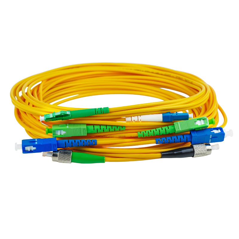
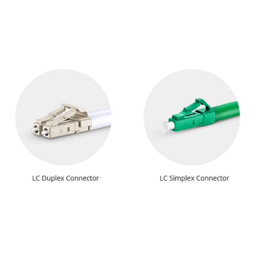
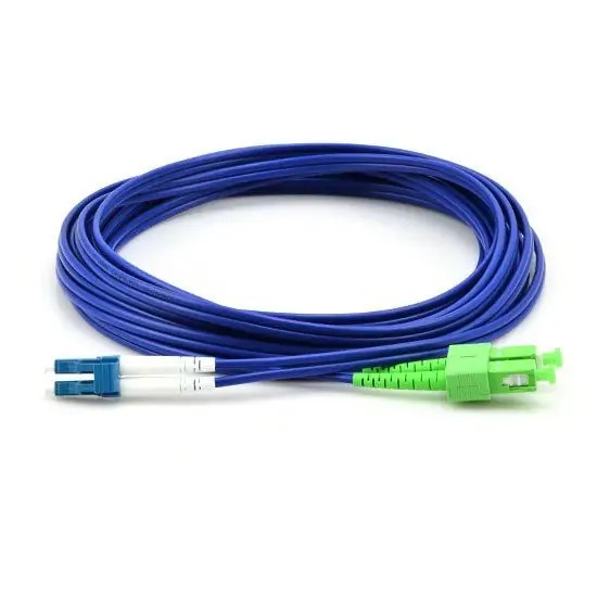
LC, SC, FC, or ST connectors;
UPC or APC polishing;
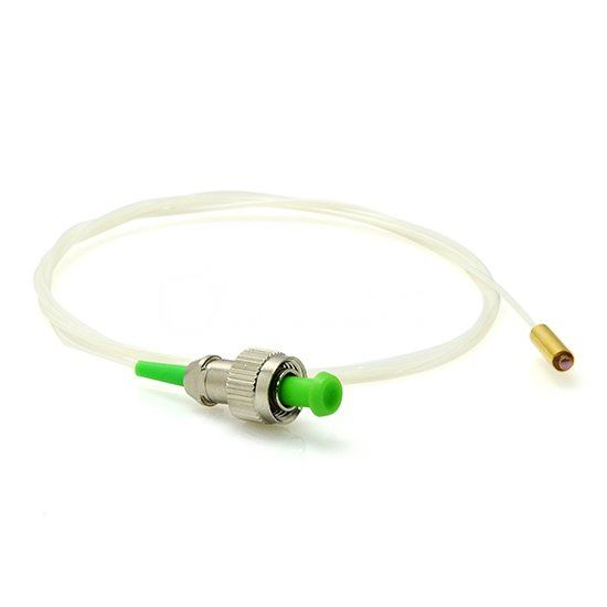
Connectorized or unterminated fiber leads;
Required pigtail or cable length.
Using incompatible fiber types or connector polish combinations may introduce additional loss, reflection, or connection problems.
In-Line VOA or Fixed Optical Attenuator?
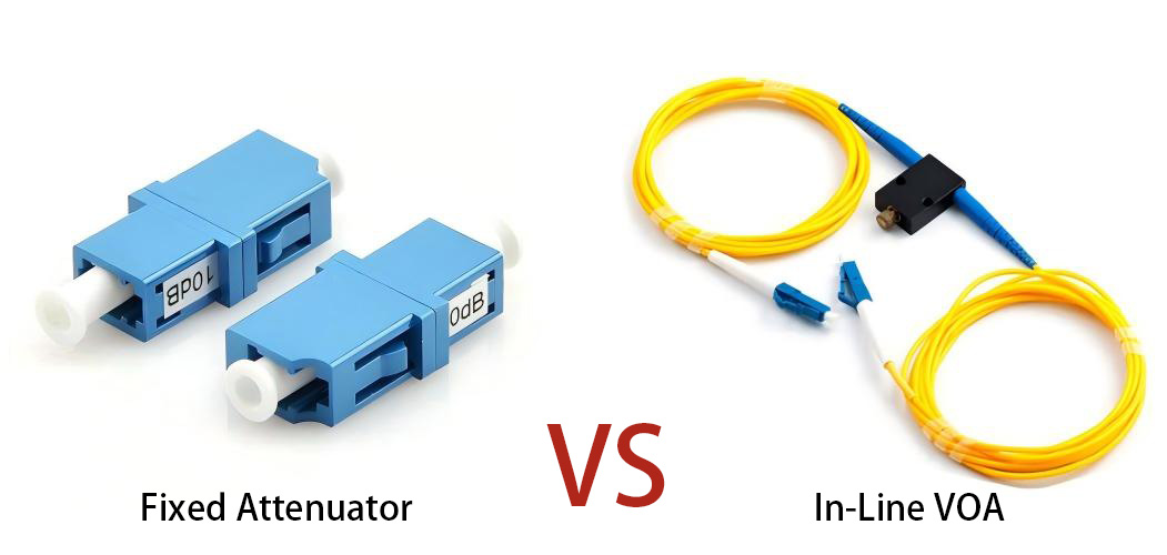
A variable attenuator is appropriate when the optical power must be adjusted during testing, installation, calibration, or system operation.
A fixed optical attenuator is generally more suitable when:
The required attenuation value is already known;
The attenuation will not need to be changed;
Compact size and low cost are the main priorities;
The component will remain permanently installed.
In many engineering environments, a VOA is used first to determine the correct attenuation value. A fixed attenuator can then be installed in the final system when ongoing adjustment is unnecessary.
Firsol In-Line Variable Optical Attenuator Options
Firsol provides manually adjustable in-line VOAs for fiber optic communication, laboratory, testing, and equipment-integration applications.
Depending on the required configuration, available options may include:
Single-mode and multimode fiber;
Wavelength options for 1310 nm, 1490 nm, and 1550 nm applications;
LC, SC, FC, and ST connector interfaces;
UPC and APC connector polishing;
Customized fiber or cable lengths;
Different attenuation ranges;
Connectorized or application-specific configurations.
Before selecting a VOA, customers should specify the operating wavelength, fiber type, required attenuation range, connector type, polishing type, cable length, and maximum optical power. Providing these details allows the VOA configuration to be matched more accurately to the optical system.
Conclusion
An in-line variable optical attenuator is a practical tool for controlling optical power without interrupting the fiber link. It can help engineers protect receivers, simulate transmission loss, evaluate receiver sensitivity, manage amplifier input or output levels, and establish repeatable test conditions.
The most suitable VOA is determined not only by its attenuation range, but also by its insertion loss, repeatability, return loss, polarization performance, power-handling capability, wavelength, and fiber interface.
Careful specification of these parameters provides more reliable measurements, more stable optical links, and better compatibility with the surrounding fiber optic equipment.