What Is Fiber Optics? How It Works, Types, and Applications
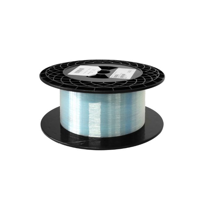
Fiber optics is the technology of guiding light through thin strands of glass or plastic. In communications, it carries information between transmitters and receivers as modulated optical signals. It also supports applications such as sensing, medical imaging, and the delivery of laser light.
The practical appeal is straightforward: optical fiber can carry large amounts of information over long distances, and the optical signal is immune to electromagnetic interference. However, fiber is not a complete network on its own. The light source, receiver, connections, and installation all affect how well a system performs.
This guide explains the fundamentals of fiber optics, the difference between single-mode and multimode fiber, and the decisions that matter when connecting real equipment.
Fiber Optics, Optical Fiber, and Fiber Optic Cable: What Is the Difference?
These terms describe related but different things:
Term | Meaning | Example |
|---|---|---|
Fiber optics | The technology of guiding and using light in optical fibers | An optical communication system |
Optical fiber | The individual waveguide that carries light | A glass fiber inside a cable |
Fiber optic cable | One or more optical fibers combined with mechanical protection | An indoor distribution cable |
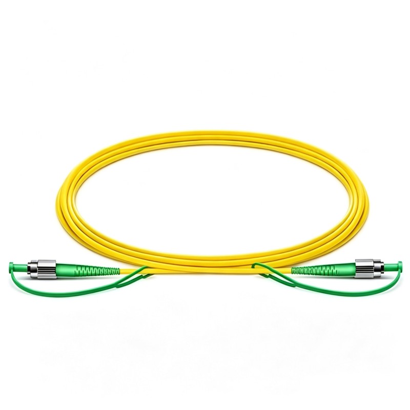
Fiber patch cable | A connectorized cable used to connect equipment or patch panels | An LC-to-LC duplex patch cord |
Fiber optic internet | An internet service delivered using fiber somewhere in its access infrastructure | Fiber-to-the-home service |
Understanding the distinction prevents a common purchasing mistake: choosing a cable by connector shape alone. Two cables can have similar connectors but contain different fibers or support different optical interfaces.
For cable construction, jackets, and assembly options, see our guide to what a fiber optic cable is and how it works.
How Does Fiber Optics Work?
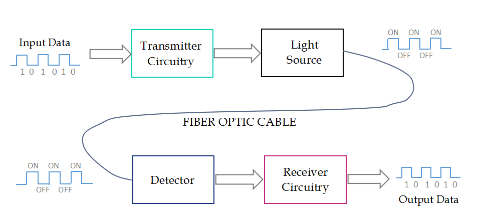
A communication link has three main stages: generating an optical signal, guiding it through fiber, and recovering the information at the receiver.
1. The transmitter encodes information onto light
A transmitter accepts an electrical data signal and uses a light source, often a laser, to produce a modulated optical signal. Some systems use LEDs. The appropriate source depends on the transmission standard and application.
Simple systems can represent information by switching light on and off. More advanced systems use additional amplitude levels or other modulation methods. Consequently, “a pulse of light equals one bit” is a useful introductory picture, but it does not describe every optical network.
2. The fiber guides the optical signal
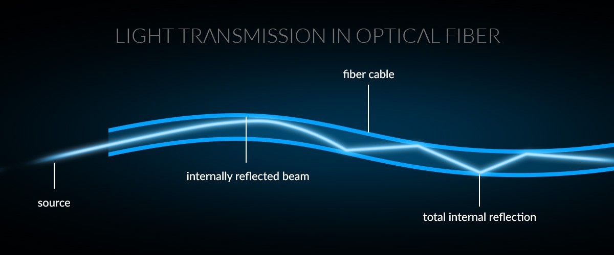
In conventional communication fiber, the central core is surrounded by cladding with a lower refractive index. This structure guides light along the fiber.
Total internal reflection provides an accessible explanation: light launched under suitable conditions remains guided instead of simply passing out through the side. A more complete description uses optical modes—the field patterns that can propagate through the waveguide.
The cladding is an optical layer, not a mirror coating. A separate polymer coating protects the glass mechanically. The finished cable provides further protection against handling and installation stresses.
3. The receiver recovers the information
At the far end, a photodetector converts the received light into an electrical signal. Receiver electronics process that signal and recover the transmitted information.
The receiver needs an appropriate optical power level and sufficient signal quality. Too much loss can make the signal unreadable, while excessive received power can overload some receivers. A working link therefore requires compatible equipment and a suitable optical budget, not just an unbroken fiber.
Single-Mode vs. Multimode Fiber
The main distinction is the number of spatial modes the fiber supports at its intended operating wavelength.
Property | Single-mode fiber | Multimode fiber |
|---|---|---|
Guiding behavior | Supports the fundamental spatial mode in its specified single-mode range | Supports multiple spatial modes |
Typical core size | Approximately 8–10 µm for common communication fibers | 50 µm or 62.5 µm |
Common cabling designations | OS1 and OS2 | OM1, OM2, OM3, OM4, and OM5 |
Familiar applications | Access networks, campus links, metropolitan and long-haul networks | Short-reach data center and enterprise links |
Typical wavelength examples | 1310 nm and 1550 nm | 850 nm; some systems use the 1300 nm region |
Important design consideration | Loss, dispersion, and optical interface compatibility | Modal bandwidth, loss, and optical interface compatibility |
The dimensions and wavelengths above describe common communication products, not every specialty fiber. Most standard glass communication fibers have a 125 µm cladding diameter.
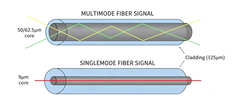
Single-mode fiber avoids the intermodal dispersion associated with multiple spatial modes. It does not eliminate all dispersion or attenuation. Multimode fiber can support high data rates over shorter links, but the permitted distance depends on the fiber grade and transceiver standard.
Neither type is automatically the cheaper solution. Compare the complete link, including optical modules, cable assemblies, installation, and the infrastructure already in place.
How Fast Is Fiber Optics, and How Far Can It Reach?
There is no single speed or distance for “fiber optics.” A cable does not independently set the network data rate. The optical interfaces, modulation, fiber characteristics, and channel design work together.
These familiar 10 Gigabit Ethernet examples show why the interface designation matters:
Optical interface | Fiber | Example specified reach |
|---|---|---|
10GBASE-SR | OM3 multimode | Up to 300 m |
10GBASE-SR | OM4 multimode | Up to 400 m |
10GBASE-LR | Suitable single-mode fiber | Up to 10 km |
These are interface-specific examples documented in Cisco's SFP+ specifications, not universal limits for the fibers. The channel must also meet the applicable loss and other requirements.
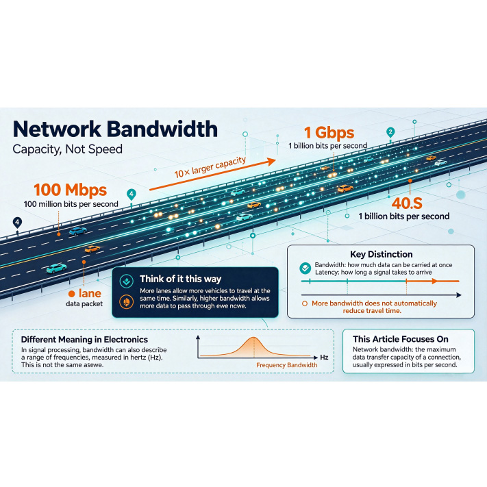
Bandwidth and latency are different. Bandwidth describes how much information a system can carry per unit time; latency describes how long delivery takes. Fiber supports high-capacity links, but end-to-end latency also includes route length, switching, processing, and congestion. It is inaccurate to say that every fiber link has less latency than every copper link.
Why a link can fail within its advertised distance
Consider a hypothetical 200 m connection using 10GBASE-SR modules and OM3 cable. The length is within the example reach above, but the link may still fail if a connector is contaminated, the transmit and receive paths are reversed, or excessive connection loss reduces received power.
This is why distance is only one check. Verify interface compatibility, polarity, end-face condition, and channel loss as well.
Can One Optical Fiber Carry Traffic in Both Directions?
Yes. The number of fibers and the direction of communication are separate concepts.
A common duplex link uses two fibers: one carries traffic from device A to device B, and the other carries the return traffic. A single-fiber bidirectional system can instead use paired optical interfaces with different transmit and receive wavelengths on the same strand.
For purchasing, distinguish these terms:
Simplex cable: a cable containing one fiber.
Duplex cable: a cable containing two fibers.
Full-duplex communication: simultaneous transmission in both directions.
A simplex cable is therefore not inherently limited to one-way communication. Conversely, a duplex cable should not be classified as a “half-duplex cable” or a “full-duplex cable” based only on its construction. The equipment determines the communication arrangement.
What Is Fiber Optics Used For?
Telecommunications and internet access
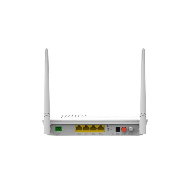
Optical networks connect cities, carry backbone traffic, and serve residential and business customers. In a fiber-to-the-home installation, optical fiber reaches the premises, where an optical network terminal interfaces with the customer's network.
The internet plan, access architecture, customer equipment, and Wi-Fi network can still limit user experience. Having a fiber connection does not mean every device receives the maximum advertised speed continuously.
Data centers and enterprise networks
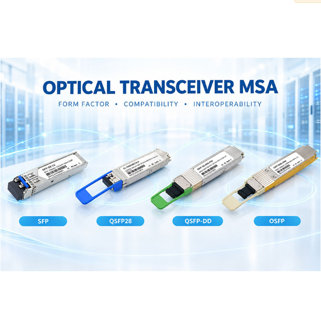
Fiber links connect switches, storage systems, and other network equipment. Interface choices vary with distance, port density, and the network design. Some links use two fibers with LC connectors; parallel optical interfaces may require multiple fibers and MPO-style connectivity.
For a procurement team, the useful starting point is the exact optical module part number—not simply a request for a “high-speed fiber cable.”
Industrial communication
Optical fiber is useful where electrical noise makes copper communication difficult. An all-dielectric cable can also avoid a conductive path between locations. A cable containing metal armor or other metallic components, however, requires separate consideration of those components.
Sensing, medical systems, and laboratories
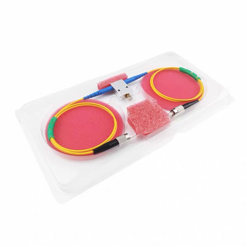
Fiber is used beyond data transmission. Applications include measuring changes in physical conditions, delivering light to instruments, and guiding laser energy. These systems may require specialty fibers selected for wavelength, numerical aperture, polarization behavior, or optical power handling.
A standard OS2 network patch cable is not a universal substitute for a specialty optical assembly.
Fiber Optics vs. Copper: Advantages and Limitations
Consideration | Fiber optics | Copper cabling |
|---|---|---|
Signal medium | Guided light | Electrical signals |
Electromagnetic interference | The guided optical signal is immune to EMI | Performance depends on cable design, shielding, installation, and environment |
Reach | Appropriate optical systems support short through long-distance links | Reach depends on the interface and cable category |
Power delivery | Ordinary all-fiber cables do not provide Ethernet electrical power | Suitable twisted-pair systems can support Power over Ethernet |
Handling | Requires clean interfaces and control of bending and pulling forces | Also has bend, pulling, termination, and installation requirements |
Cost | Depends on optics, cabling, installation, and existing infrastructure | Depends on interface, cable category, installation, and power needs |
Copper is not limited to 10 Gbps. For example, Category 8 cabling supports 25/40GBASE-T channels up to 30 m under the relevant requirements. Avoid broad comparisons that treat all copper products as one technology.
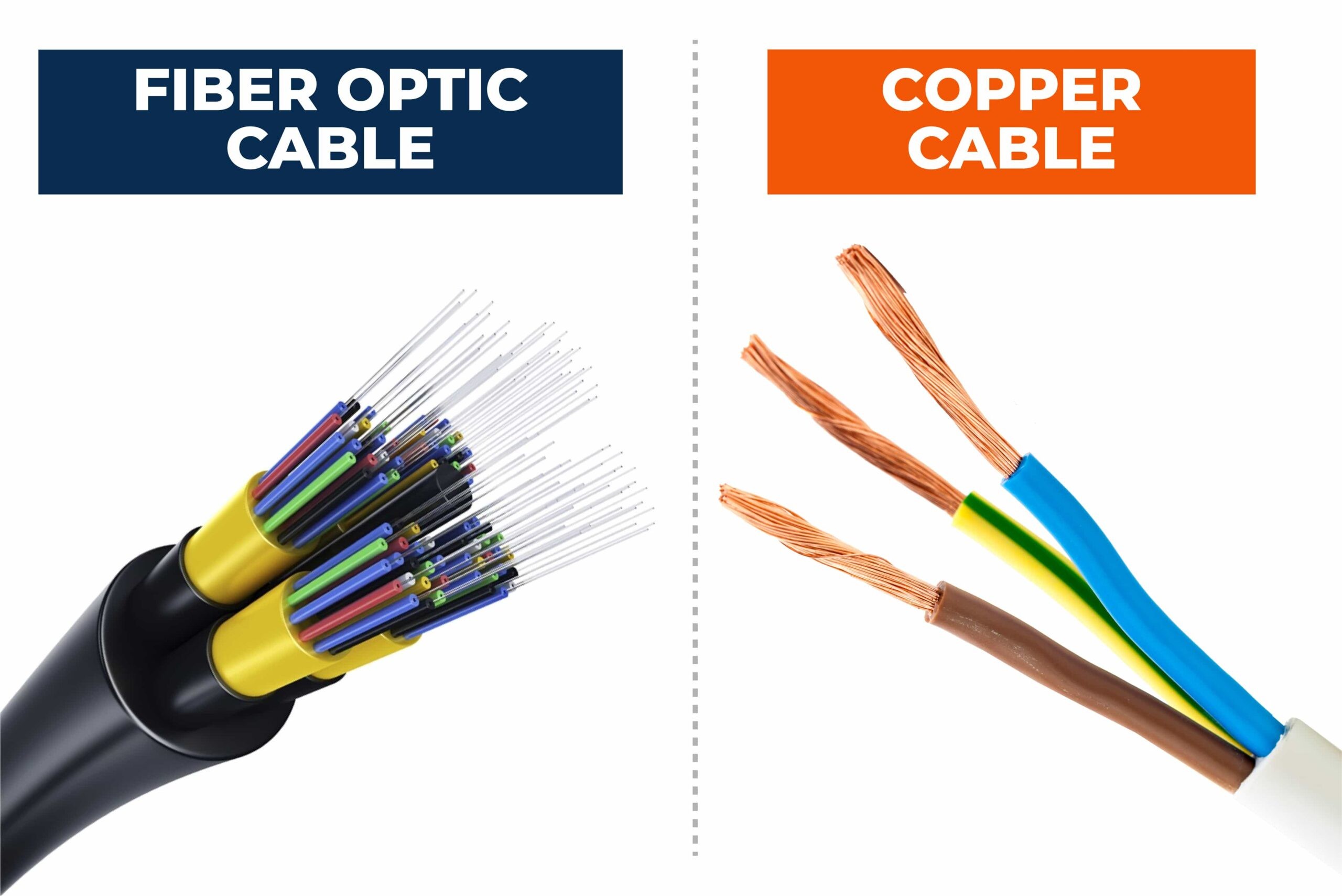
Fiber also has limitations. It can suffer from contamination, excessive bending, damaged terminations, and mismatched components. Its resistance to EMI does not make it immune to physical damage or unauthorized interception. Environmental suitability depends on the complete cable design and its ratings.
How to Specify a Fiber Optic Connection
Before ordering a cable assembly, collect the following information:
Equipment and optical interface. Record the module part numbers, data rate, operating wavelengths, and supported fiber type.
Route and distance. Include patch panels, intermediate connections, and sensible routing allowance.
Fiber specification. Match OS2, OM3, OM4, or another required type to the system documentation.
Connector and polish. Confirm each end independently. Matching connector shape does not guarantee matching end-face geometry.
Fiber count and polarity. Check the transmit-to-receive mapping. For MPO assemblies, also verify the pin configuration and interface-specific fiber mapping.
Installation environment. Specify indoor or outdoor use, mechanical protection, and the required jacket or fire rating.
Performance requirements. Identify allowable channel loss and any application-specific return-loss or polarization requirements.
UPC and APC describe different end-face geometries. Do not directly mate an APC connector to a UPC interface. Likewise, do not assume that a cable meets an equipment requirement because its jacket has a familiar color; check its markings and specification.
For ordinary two-fiber connections, a custom OS2 duplex fiber patch cable may be appropriate when the equipment specifies single-mode fiber. High-density designs may instead require MTP® trunk assemblies with the correct fiber count and mapping.
Common Fiber Optic Problems and What to Check
Symptom | Possible causes | Useful first checks |
|---|---|---|
No link | Incorrect polarity, incompatible interfaces, disconnected or damaged fiber | Check module specifications and transmit-to-receive paths |
Unexpectedly low received power | Dirty interfaces, excessive connection loss, tight bends | Inspect end faces and routing; measure optical power |
Intermittent errors | Marginal signal quality, unstable connections, equipment issues | Check diagnostics, channel loss, and connector condition |
Loss after a cable move | Bend stress, a disturbed connection, or physical damage | Inspect the changed route and connections |
These are starting points, not definitive diagnoses. Use a light source and power meter or an optical loss test set to measure end-to-end insertion loss. An OTDR helps locate and characterize events such as splices, reflections, and faults along a fiber; it does not replace every other test.
Inspect connector end faces with suitable equipment, clean when needed, and inspect again before mating. Never look directly into a fiber or optical port to check whether it is transmitting: communication light is often invisible.
Frequently Asked Questions
Is fiber optics the same as fiber internet?
No. Fiber optics is the broader technology. Fiber internet is one application, alongside private networks, sensing systems, and other optical equipment.
Are optical fibers made of glass or plastic?
Both exist. Glass fibers are common in telecommunications and data networks. Plastic optical fibers serve other applications with different distance, bandwidth, and handling requirements.
Is single-mode fiber always better than multimode?
No. Select the type supported by the optical interface and suitable for the route. Existing infrastructure, module cost, distance, and upgrade requirements all affect the decision.
Does fiber need electricity?
The fiber itself is a passive waveguide. Communication transmitters, receivers, and network equipment need power. An all-fiber patch cable does not supply electrical power to an endpoint in the way a suitable PoE copper connection can.
Can a fiber optic cable be bent?
Yes, within its specified bend-radius limits. Observe the manufacturer's installation and operating limits, which may differ. Bend-insensitive fiber still has handling limits.
Does installing fiber automatically improve internet speed?
Not necessarily. Fiber can support high-capacity transmission, but actual throughput also depends on the service plan, equipment, configuration, and bottlenecks elsewhere in the network.
Planning Your Fiber Connection
Start with the optical interfaces and the link requirements, then select a compatible cable assembly. This approach helps avoid ordering the correct connector on the wrong fiber, or the right fiber with an unsuitable polarity or polish.
Explore FIRSOL fiber optic cables and custom assemblies. For help specifying a connection, send your equipment or module part numbers, required length, connector details, fiber count, and installation environment to [email protected].