What Is a Fiber Optic Cable and How Does It Work?
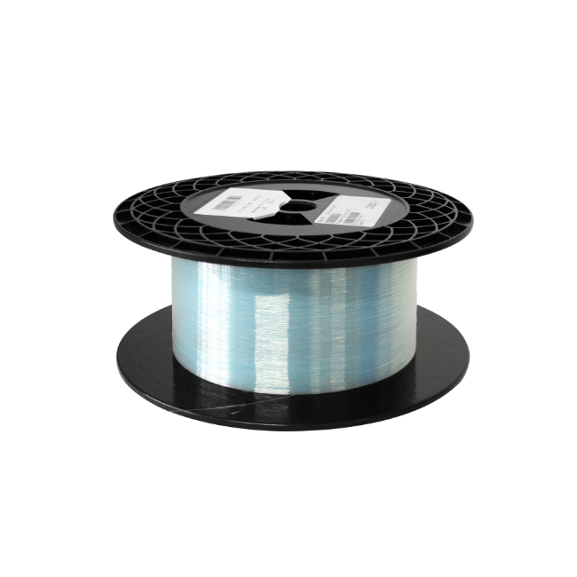
A fiber optic cable is a transmission medium that carries data as pulses of light through thin strands of glass or plastic fiber. Unlike copper cables, which transmit electrical signals, fiber optic cables guide light to deliver high bandwidth over short, medium, or long distances.
Fiber optic cables are widely used in telecommunications networks, data centers, broadband systems, enterprise networks, industrial facilities, and research laboratories. Their low attenuation, resistance to electromagnetic interference, and ability to support high data rates make them an essential part of modern communication infrastructure.
However, “fiber optic cable” is a broad term. Different cables use different fiber types, connector interfaces, cable constructions, fiber counts, and jacket materials. This guide explains how fiber optic cables work, what they are made of, their main types, advantages and limitations, and how to select the right cable for an application.
What Is a Fiber Optic Cable?
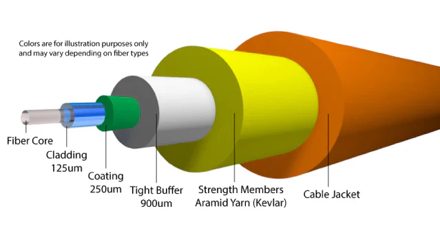
A fiber optic cable is a protected cable assembly containing one or more optical fibers that carry light between a transmitter and a receiver.
It is important to distinguish an optical fiber from a complete fiber optic cable:
An optical fiber is the individual glass or plastic waveguide through which light travels.
A fiber optic cable is the complete assembly that protects one or more optical fibers and prepares them for installation or connection.
In addition to the optical fibers, a cable may contain protective coatings, buffers, strength members, water-blocking materials, armor, and an outer jacket. Some fiber cables are supplied without connectors for field installation, while fiber patch cables and pre-terminated assemblies have connectors installed at one or both ends.
Common fiber connector types include LC, SC, FC, ST, E2000, and MTP®/MPO. The appropriate connector depends on the equipment interface, installation density, fiber count, polishing requirement, and intended application.
Fiber optic cables can carry network data, telephone signals, video, control signals, and measurement signals. They are also used to deliver optical power and connect components in sensing, medical, industrial, and laboratory systems.
How Does a Fiber Optic Cable Work?
A fiber optic communication link generally consists of three stages:
A transmitter converts information into a modulated optical signal.
The optical fiber guides the light to its destination.
A receiver detects the light and converts it into an electrical signal.
1. Converting Data into Light
At the transmitting end, an optical transmitter receives an electrical data signal from network or communication equipment. A laser diode, VCSEL, or LED then converts that information into modulated light.
The light may be turned on and off rapidly or modulated using more advanced methods to encode digital information. The wavelength and light source depend on the fiber type, transmission standard, distance, and required data rate.
Common operating wavelengths include:
850 nm for many short-reach multimode links
1310 nm for single-mode transmission and some multimode applications
1550 nm for long-distance transmission and wavelength-division multiplexing systems
Other wavelengths are used in specialty communication, sensing, laser, medical, and laboratory applications.
2. Guiding Light Through the Fiber
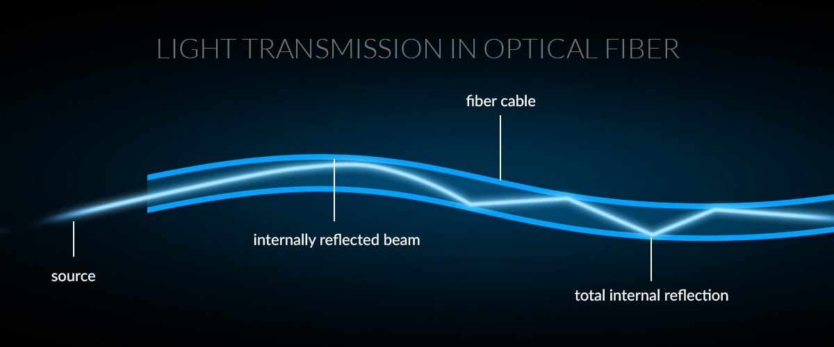
An optical fiber consists primarily of a core surrounded by cladding. The core has a slightly higher refractive index than the cladding, allowing light to remain guided along the fiber when launched under appropriate conditions.
This guiding mechanism is commonly explained through total internal reflection. In practical fiber systems, however, light propagates as electromagnetic modes determined by the fiber’s refractive-index profile, geometry, and operating wavelength.
Single-mode fiber has a relatively small core and is designed to support only the fundamental propagation mode at its specified operating wavelengths. This reduces modal dispersion and supports high-bandwidth transmission over long distances.
Multimode fiber has a larger core and supports multiple propagation modes. It is widely used for shorter links because it can work with cost-effective optical interfaces, but modal dispersion generally limits its transmission distance at higher data rates.
3. Receiving the Optical Signal
At the receiving end, a photodetector detects the incoming light and converts it into an electrical signal. The receiving equipment then processes the signal and recovers the transmitted data.
The maximum distance of a fiber link is not determined by the cable alone. It depends on factors including:
Fiber type
Operating wavelength
Transmitter output power
Receiver sensitivity
Data rate
Connector and splice losses
Fiber attenuation
Dispersion
Total optical link budget
Long-distance systems may also use optical amplifiers or signal regeneration equipment to maintain transmission performance.
What Is a Fiber Optic Cable Made Of?
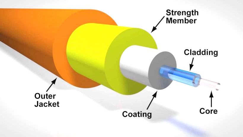
A fiber optic cable contains several layers, each serving a different optical, mechanical, or environmental function.
Core
The core is the central region through which the optical signal propagates.
Common core sizes include approximately:
8 to 10 µm for standard single-mode fiber
50 µm for OM2, OM3, OM4, and OM5 multimode fiber
62.5 µm for OM1 multimode fiber
These are nominal or typical dimensions. Exact parameters depend on the applicable fiber standard and manufacturer specification.
Cladding
The cladding surrounds the core and has a slightly lower refractive index. This difference helps confine and guide light within the core.
Most standard communication fibers have a cladding diameter of 125 µm, regardless of whether the fiber is single-mode or multimode.
Protective Coating
A polymer coating is applied over the glass cladding to protect the fiber against moisture, abrasion, and microscopic surface damage.
A commonly used coated fiber has an outside diameter of approximately 250 µm. The coating is mechanically protective and is different from the optical cladding.
Buffer
A buffer provides additional protection and makes the optical fiber easier to handle during cable manufacturing, termination, and installation.
Two common constructions are:
Tight-buffered fiber: The buffer fits closely around the coated fiber and is commonly used in indoor cables, patch cords, and cable assemblies.
Loose-tube fiber: One or more fibers are placed inside a protective tube with room for movement. This construction is commonly used in outdoor and high-fiber-count cables.
Strength Members
Strength members help the cable withstand pulling forces during installation and normal use. Common materials include aramid yarn and fiberglass-reinforced plastic.
Their purpose is to keep excessive tensile stress away from the optical fibers.
Outer Jacket
The outer jacket protects the complete cable from mechanical damage and environmental exposure. Jacket selection depends on the installation location, fire-safety requirements, temperature, chemical exposure, moisture, and applicable regulations.
Common jacket or flame-rating designations include PVC, LSZH, OFNR, and OFNP. These terms are not interchangeable, and the appropriate option should be selected according to the installation environment and local code requirements.
Cable component | Primary function |
|---|---|
Core | Carries the optical signal |
Cladding | Helps guide and confine light |
Coating | Protects the glass fiber |
Buffer or tube | Adds mechanical and environmental protection |
Strength member | Helps withstand pulling forces |
Outer jacket | Protects the complete cable assembly |
Single-Mode vs. Multimode Fiber Optic Cable
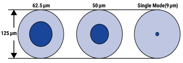
Single-mode and multimode are the two main categories of communication fiber.
Feature | Single-mode fiber | Multimode fiber |
Typical core size | Approximately 9 µm | 50 or 62.5 µm |
Common categories | OS1 and OS2 | OM1, OM2, OM3, OM4, and OM5 |
Typical light source | Laser | LED or VCSEL |
Transmission distance | Generally longer | Generally shorter |
Modal dispersion | Minimal | Higher |
Common applications | Telecom, FTTH, campus backbones, long-distance links | Data centers, LANs, equipment rooms, short-reach links |
Single-mode fiber is commonly selected for long-distance and high-capacity transmission. OS2 is widely used in outdoor, campus, telecom, data center interconnect, and broadband applications.
Multimode fiber is widely used for shorter connections inside buildings and data centers. OM3 and OM4 are commonly associated with high-speed Ethernet links using VCSEL-based transceivers, while OM1 and OM2 are more common in legacy systems.
Neither fiber type is universally better. The correct choice depends on transmission distance, data rate, optical transceiver, installed infrastructure, upgrade plans, and overall system cost.
Common Types of Fiber Optic Cables
Fiber optic cables can also be classified according to their construction, fiber count, connector configuration, and installation environment.
Simplex and Duplex Fiber Cables
A simplex cable contains one optical fiber and provides a single optical path. It is used in applications requiring one-way transmission or in systems that send and receive over the same fiber using different wavelengths.
A duplex cable normally contains two fibers. One fiber can be used for transmission and the other for reception, making duplex assemblies common in bidirectional network connections.
Fiber Patch Cables
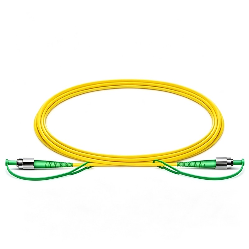
A fiber patch cable is a pre-terminated assembly with a fiber connector installed at each end. It is used to connect transceivers, switches, patch panels, test equipment, and other optical devices.
Patch cables are available in different fiber modes, connector combinations, lengths, cable diameters, jacket materials, and polishing types.
Fiber Pigtails
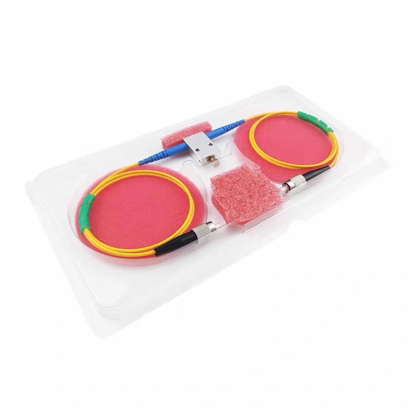
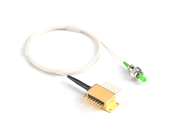
A fiber pigtail has a connector installed on one end and exposed fiber on the other. The unterminated end is normally fusion-spliced to another fiber in a distribution box, patch panel, enclosure, or optical assembly.
Tight-Buffered and Loose-Tube Cables
Tight-buffered cables are often selected for indoor installations and patch cable assemblies because their fibers are relatively easy to handle and terminate.
Loose-tube cables provide room for the fibers to move within protective tubes and are commonly selected for outdoor, long-distance, and high-fiber-count installations.
Ribbon Fiber Cables
Ribbon cables arrange multiple fibers in a flat, parallel structure. This design can support high fiber density and mass fusion splicing, making it useful in data centers, access networks, and high-fiber-count infrastructure.
Armored Fiber Cables
Armored cables include an additional protective layer to improve resistance to crushing, impact, or rodent damage.
Armor does not automatically make a cable suitable for every outdoor or direct-burial environment. Moisture protection, jacket material, UV resistance, temperature rating, and installation method must also be considered.
MTP®/MPO Fiber Cables
MTP®/MPO cables use multi-fiber connectors that can terminate several optical fibers within one compact interface. Common configurations include 8, 12, 16, and 24 fibers, although other configurations are available.
These assemblies are widely used for high-density data center cabling, parallel-optics links, trunk connections, breakout applications, and high-speed network migration.
Specialty Fiber Cables
Specialty cable assemblies are designed for applications beyond standard data communication. Examples include:
Bend-insensitive fiber cables
High-power fiber assemblies
Wavelength-specific fiber cables
Sensing fibers
Harsh-environment cables
Laboratory and medical fiber assemblies
The fiber type, connector, polishing method, handling requirements, and performance specifications must be matched to the intended optical system.
Common Fiber Optic Connector Types
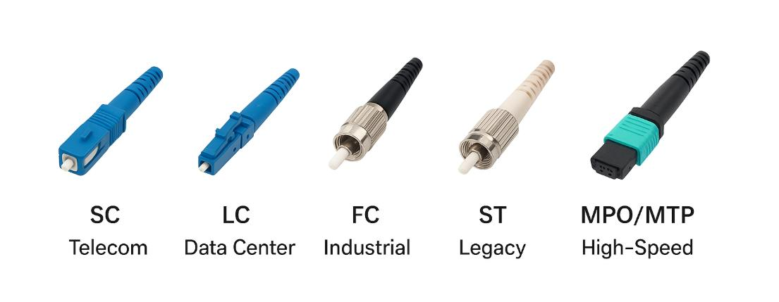
The connector determines how a fiber cable mates with equipment, adapters, patch panels, and other cable assemblies.
Connector | Key characteristic | Common applications |
LC | Compact connector with latch mechanism | Transceivers, data centers, patch panels |
SC | Push-pull coupling design | Telecom, FTTH, enterprise networks |
FC | Threaded coupling mechanism | Test equipment, laboratories, precision systems |
ST | Bayonet-style coupling | Industrial and legacy networks |
MTP®/MPO | Multi-fiber interface | High-density and parallel-optics links |
Fiber connectors may also use different end-face polishing methods.
UPC connectors use an ultra-physical-contact polish and are widely used in digital communication systems. APC connectors have an angled end face that helps reduce back reflection and are commonly used in PON, analog optical, sensing, and reflection-sensitive applications.
UPC and APC interfaces should not be directly mated because their end-face geometries are different. Connector type, polish, fiber mode, and adapter compatibility should all be confirmed before installation.
Advantages of Fiber Optic Cables
Fiber optic cables offer several important advantages over copper transmission media.
High Bandwidth
Optical fiber can support high-capacity transmission and is used in network standards ranging from relatively low data rates to 400G, 800G, and beyond.
Actual bandwidth depends on the complete system, including the fiber type, transceivers, modulation method, wavelength, distance, and link design.
Long Transmission Distance
Fiber generally supports longer transmission distances than copper at comparable data rates. Single-mode fiber is particularly well suited to telecom, metropolitan, campus, and long-distance connections.
Low Attenuation
Optical fiber has relatively low signal attenuation, especially within commonly used communication wavelength windows. This allows signals to travel long distances with fewer intermediate active devices.
Resistance to Electromagnetic Interference
Because the signal is transmitted optically rather than electrically, the glass fiber is not affected by electromagnetic or radio-frequency interference. This makes fiber useful near motors, power equipment, industrial machinery, and other sources of electrical noise.
Electrical Isolation
Standard all-dielectric fiber can provide electrical isolation between connected devices. However, some fiber cables contain conductive armor, messenger wires, tracing conductors, or power conductors and therefore require different handling and grounding considerations.
Small Size and Low Weight
Optical fibers are small and lightweight compared with many copper cables of comparable transmission capacity. High-fiber-count cable designs can provide substantial connection density within conduits, trays, and equipment spaces.
Limitations and Installation Considerations
Fiber optic cables also have practical limitations.
Connector end faces are sensitive to dust, oil, and contamination. Even small particles can increase insertion loss, cause reflection, or damage mating surfaces. Connectors should be inspected and cleaned using appropriate procedures before connection.
The cable’s minimum bend radius and maximum tensile load must be observed during installation. Excessive bending, pulling, crushing, or twisting can increase optical loss or permanently damage the fibers.
Fiber termination, fusion splicing, end-face inspection, and optical testing require suitable tools and trained personnel. Depending on the link and application, testing may include:
Visual end-face inspection
Insertion loss testing
Return loss testing
Optical power measurement
Polarity verification
OTDR testing
The selected cable must also match the optical interfaces at both ends. Fiber mode, connector type, polishing method, wavelength, polarity, and transmission standard all affect compatibility.
Where Are Fiber Optic Cables Used?
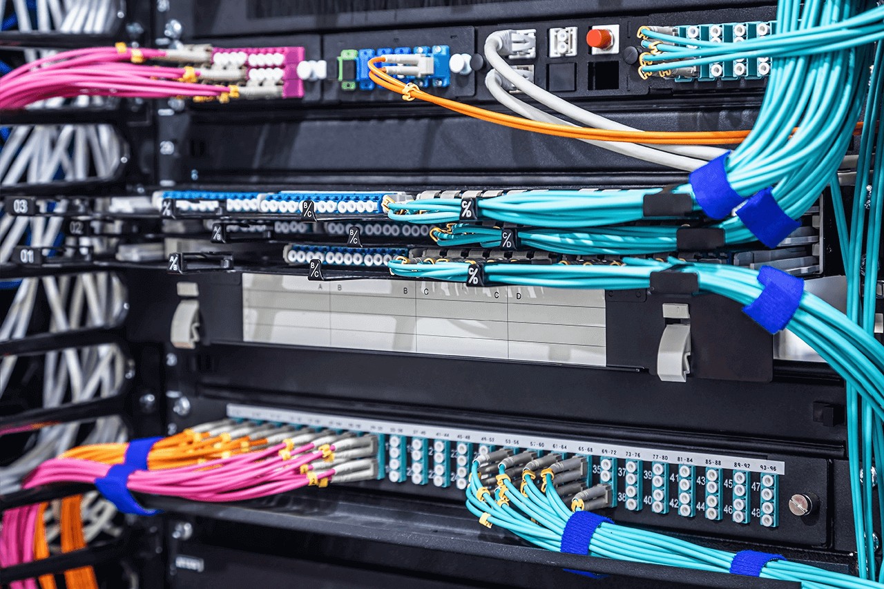
Fiber optic cables support a wide range of communication and optical applications, including:
Telecommunications networks
Data centers
Enterprise and campus networks
FTTH and passive optical networks
Cable television systems
Industrial control and automation
Security and surveillance networks
Medical equipment and imaging
Fiber optic sensing
Research laboratories
Military and aerospace systems
Optical component manufacturing and testing
The required cable construction can differ significantly between these applications. A short indoor data center patch cord, for example, has different requirements from an outdoor loose-tube cable or a polarization-maintaining laboratory assembly.
How to Choose the Right Fiber Optic Cable
Selecting a fiber optic cable requires more than choosing a connector and length.
1. Determine the Data Rate and Transmission Distance
Start with the network standard, required data rate, and total link distance. These factors help determine whether single-mode or multimode fiber is appropriate.
2. Match the Optical Equipment
Confirm the fiber mode, wavelength, and connector interface supported by the transceivers or optical equipment at both ends.
3. Select the Connector and Polish
Choose connector types compatible with the equipment. Confirm whether UPC or APC polishing is required and avoid directly mating incompatible end faces.
4. Determine the Fiber Count
Select simplex, duplex, or multi-fiber construction according to the number of optical channels, redundancy requirements, and future expansion plan.
5. Choose the Cable Construction
Consider whether the installation requires tight-buffered, loose-tube, ribbon, breakout, armored, or another specialized construction.
6. Select the Jacket and Fire Rating
Choose a jacket appropriate for the installation environment and applicable regulations. Indoor plenum spaces, risers, industrial locations, outdoor routes, and laboratory systems may require different materials and ratings.
7. Verify Optical and Mechanical Performance
Confirm requirements such as insertion loss, return loss, polarity, operating temperature, tensile strength, minimum bend radius, environmental resistance, and expected service life.
Firsol provides fiber optic cables and custom cable assemblies for data centers, telecommunications networks, enterprise infrastructure, fiber manufacturing, and laboratory systems. Available configurations vary by product and may include different fiber types, connectors, polishing methods, lengths, cable diameters, fiber counts, polarity methods, and jacket materials.
Frequently Asked Questions
Do fiber optic cables carry electricity?
The glass or plastic optical fiber carries light rather than electrical current. However, some cable constructions include metallic armor, messenger wires, tracing conductors, or power conductors. The complete cable construction should therefore be checked before treating it as fully nonconductive.
Is fiber optic cable faster than copper cable?
Fiber optic systems generally support higher transmission capacity and longer distances than copper systems. However, actual speed is determined by the complete communication standard, transceivers, network equipment, fiber type, and link design—not by the cable alone.
How far can a fiber optic cable transmit data?
There is no single maximum distance for all fiber optic cables. Transmission distance depends on fiber type, wavelength, data rate, transmitter power, receiver sensitivity, attenuation, dispersion, connector loss, splice loss, and the total optical link budget.
A multimode data center link may cover a relatively short distance, while a properly designed single-mode system can transmit signals over many kilometers.
Can fiber optic cables be installed outdoors?
Yes, but the cable must be designed for the intended outdoor environment. Depending on the installation, requirements may include UV resistance, water blocking, loose-tube construction, armor, temperature resistance, rodent protection, or direct-burial suitability.
An indoor patch cable should not be used outdoors unless its specifications explicitly permit the intended installation.
What is the difference between a fiber optic cable and a fiber patch cable?
“Fiber optic cable” is a broad term covering many cable types. A fiber patch cable is a specific pre-terminated assembly with optical connectors installed at both ends, normally used to connect equipment, transceivers, adapters, and patch panels.
Can single-mode and multimode fibers be connected?
They may be physically connected when compatible connector interfaces are used, but their core sizes and propagation characteristics are different. This mismatch can produce high loss and unreliable performance. Single-mode and multimode fiber should not normally be mixed within a properly designed communication link.
How should fiber optic connectors be cleaned?
A common procedure is “inspect, clean, and inspect again.” Use a suitable fiber inspection microscope and cleaning tools designed for the connector type. Never assume that a new connector is clean, and avoid touching the ferrule end face.
Conclusion
Fiber optic cables transmit information as light through protected glass or plastic fibers. Their high bandwidth, low attenuation, long-distance capability, and resistance to electromagnetic interference make them essential to modern communication networks and optical systems.
Choosing the right cable requires more than deciding between single-mode and multimode fiber. Connector type, polishing method, fiber count, cable construction, jacket material, installation environment, polarity, and optical performance must also be considered.
Firsol supplies standard and custom fiber optic cable assemblies for data centers, telecommunications networks, enterprise infrastructure, manufacturing, and laboratory applications. Explore our fiber optic cable categories or contact the Firsol engineering team for assistance with a specific cable requirement.