Polarization Beam Splitters & Combiners (PBS/PBC): Working Principle, Specifications, Applications and Selection Guide
Polarization plays an important role in many fiber optic systems, especially where optical signals must maintain, separate, or combine well-defined polarization states. A Polarization Beam Splitter (PBS) and Polarization Beam Combiner (PBC) are passive optical components designed specifically for this purpose.
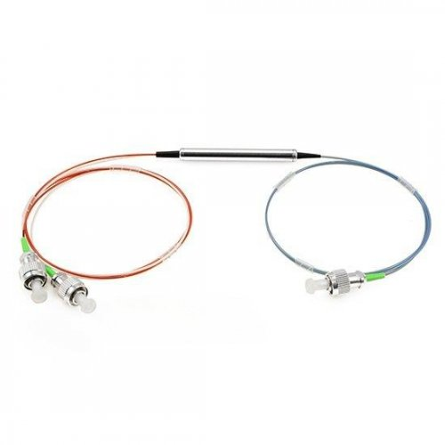
A polarization beam splitter separates an optical signal into two orthogonal polarization components, while a polarization beam combiner performs the reverse function by combining two orthogonally polarized inputs into a common output fiber. In many fiber-based designs, the same reciprocal device can operate as either a PBS or a PBC depending on the direction in which light propagates through it.
Unlike an ordinary fiber optic splitter, which divides optical power according to a coupling ratio such as 50/50 or 90/10, a PBS/PBC routes light according to its state of polarization. This makes the device particularly useful in polarization-maintaining fiber systems, optical amplifiers, fiber lasers, coherent communication systems, optical sensing, interferometers, and other polarization-sensitive applications.
This guide explains how a fiber polarization beam combiner/splitter works, how its ports and polarization axes are configured, which specifications matter most, how it differs from a conventional optical splitter, and what engineers should consider when selecting a PBS/PBC.
What Is a Polarization Beam Splitter?
A Polarization Beam Splitter, commonly abbreviated as PBS, separates light according to two mutually orthogonal polarization states.
Consider a linearly polarized optical signal entering the common port. If its polarization can be resolved into two orthogonal components, the PBS directs one component toward one output port and the orthogonal component toward the other.
In a simplified fiber configuration:
Common Input → PBS → Polarization 1 + Polarization 2
The two output ports are normally connected to polarization-maintaining fibers so that the separated polarization states can be preserved after leaving the device.
The amount of optical power appearing at each output therefore depends on the polarization state of the input rather than on a predefined splitting ratio.
For example, if the incoming polarization is aligned almost entirely with one polarization axis of the device, most optical power will be routed to the corresponding output. If the input polarization contains significant components along both orthogonal axes, optical power will appear at both outputs.
This behavior is fundamentally different from that of a 50/50 fiber coupler or PLC splitter.
What Is a Polarization Beam Combiner?
A Polarization Beam Combiner operates in the reverse direction.
Instead of separating one optical signal into two polarization components, a PBC accepts two inputs with mutually orthogonal polarization states and couples them into one common output fiber.
The basic configuration can be represented as:
Polarization 1 + Polarization 2 → PBC → Common Output
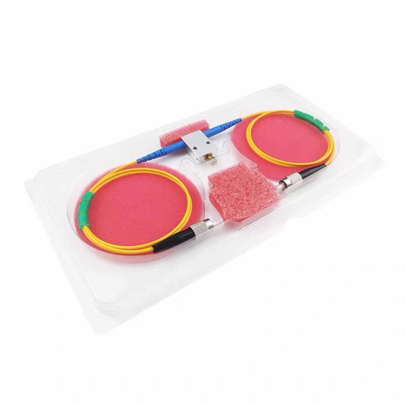
A typical fiber polarization beam combiner therefore contains two polarization-maintaining input fibers. Their polarization axes are arranged so that the two optical signals presented to the polarization-selective element are orthogonal to each other.
The common output can use either a single-mode fiber or polarization-maintaining fiber depending on the system architecture. This two-PM-port plus one-common-port configuration is widely used in commercial fiber-based PBC/PBS devices.
It is important to understand that a polarization beam combiner is a passive device. It does not amplify light or create additional optical power. Instead, it enables optical power from two suitably polarized inputs to share a common output path while minimizing loss.
How Does a Polarization Beam Combiner/Splitter Work?
The operating principle of a PBS/PBC is based on the ability of a polarization-selective optical element to distinguish between two orthogonal linear polarization states.
Inside a fiber-based device, a micro-optic polarizing or birefringent structure can direct the two polarization components along different optical paths. The exact internal construction varies between manufacturers and device architectures, so it is better to describe the device by its optical function rather than assume every PBS/PBC uses exactly the same internal element.
For example, some fiber-based polarization beam combiners use a birefringent prism to route orthogonal polarization states between the three fiber ports.
Operation as a PBS
When light enters the common port, its electric-field components along two orthogonal polarization axes are separated.
One component is coupled to Port 1, while the orthogonal component is coupled to Port 2.
In a polarization-maintaining design, the corresponding polarization is then aligned with the required axis of the PM output fiber. This enables the polarization state to remain stable as the light propagates through the downstream PM fiber system.
Operation as a PBC
The process is reversed when the device is used as a combiner.
Light entering Port 1 and Port 2 must have the appropriate orthogonal polarization orientations. The internal polarizing element directs both signals toward the common port, allowing the two optical signals to propagate through a shared output fiber.
This bidirectional behavior is why the terms Polarization Beam Combiner/Splitter, PBC/PBS, and PBS/PBC are frequently used for the same three-port fiber optic component.
Why Are Polarization-Maintaining Fibers Used?
Polarization-maintaining fiber is central to the operation of many fiber PBS/PBC designs.
Standard single-mode fiber supports two orthogonal polarization modes, but environmental disturbances such as bending, stress, pressure, and temperature variation can cause the polarization state to change during propagation.
Polarization-maintaining fiber introduces strong birefringence between its two principal axes, normally referred to as the slow axis and fast axis. When linearly polarized light is correctly launched along one of these principal axes, coupling between the two polarization modes is strongly reduced.
For a PBS/PBC, maintaining the correct polarization orientation is critical because the device relies on the distinction between orthogonal polarization states.
In a typical configuration, Port 1 and Port 2 use PM fiber, while the common Port 3 may use either standard single-mode fiber or PM fiber. FIRSOL's current PBS/PBC products support both configurations. For example, the 1550 nm model uses PM1550 fiber on Ports 1 and 2, while Port 3 can be configured with SMF-28e or PM1550 fiber.
For connectorized PM components, the relationship between the PM fiber axis and connector key is also important. FIRSOL specifies the slow axis aligned to the connector key by default, helping maintain a known polarization reference when connecting the component into a PM fiber system.
SMF Common Port vs All-PM Configuration
One of the most important choices when specifying a fiber polarization beam combiner/splitter is the fiber used at the common port.
PM + PM to SMF
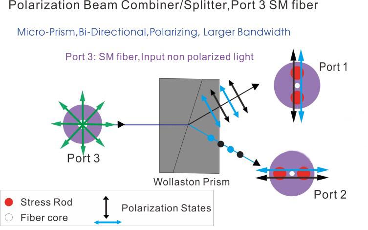
A common configuration uses two PM fibers at the polarization ports and one standard single-mode fiber at the common port.
This is useful when the purpose of the device is to combine two orthogonally polarized signals into a common optical path and there is no requirement to preserve a single defined PM axis after the signals are combined.
For example:
PM Port 1 + PM Port 2 → PBS/PBC → SM Common Port
Three PM Ports
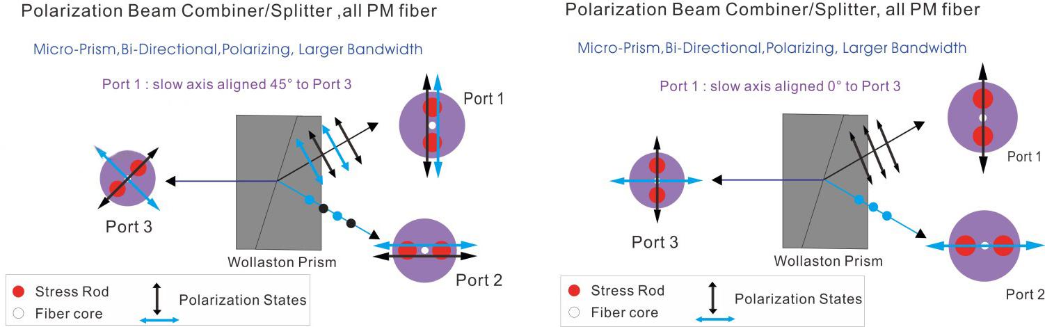
In an all-PM configuration, all three ports use polarization-maintaining fiber.
This is useful when downstream equipment requires a defined relationship between the polarization state and the fiber axes.
With FIRSOL's current products, the PM common port can be configured with its slow axis aligned with the Port 1 slow axis or at a specified orientation such as 45° relative to Port 1.
Choosing between an SMF and PM common port should therefore be based on the polarization requirements of the complete optical system rather than simply on fiber type alone.
Polarization Beam Splitter vs Polarization Beam Combiner
A PBS and PBC are best understood as two operating directions of the same basic polarization-selective function.
Characteristic | Polarization Beam Splitter | Polarization Beam Combiner |
|---|---|---|
Main Function | Separates two orthogonal polarization components | Combines two orthogonally polarized signals |
Typical Direction | One common port to two polarization ports | Two polarization ports to one common port |
Port 1 & Port 2 | PM fiber commonly used | PM fiber commonly used |
Common Port | SMF or PM fiber | SMF or PM fiber |
Key Performance Concern | Polarization separation and extinction ratio | Combination loss and polarization alignment |
Typical Applications | Polarization separation, sensing, coherent systems | Pump combining, fiber lasers, optical amplifiers |
Because many fiber PBS/PBC devices are reciprocal, the physical component can often perform either function simply by reversing the propagation direction. Both FIRSOL and other commercial fiber PBS/PBC designs describe this bidirectional operating principle.
Key Specifications of a Polarization Beam Combiner/Splitter
Choosing a PBS/PBC requires more than matching the center wavelength. Several optical parameters directly affect system performance.
Operating Wavelength
Polarization optics are wavelength dependent, so the PBS/PBC must be designed for the intended operating band.
FIRSOL currently offers polarization beam combiner/splitter products at multiple wavelengths including 532, 633, 670, 780, 850, 980, 1030, 1064, 1310, 1480, and 1550 nm.
The specified operating wavelength range varies by wavelength. For example, current FIRSOL product specifications show ±10 nm around 532/633/670 nm, ±20 nm for products such as 780/850/980/1064 nm, and ±40 nm for 1310 and 1550 nm versions.
The device should therefore be selected according to both the nominal wavelength and the actual spectral range of the optical source.
Insertion Loss
Insertion loss (IL) represents the optical power lost when light propagates through the device.
Lower insertion loss is generally preferred because it preserves more optical power for downstream components.
Insertion loss is wavelength dependent. Selected FIRSOL specifications illustrate this clearly:
Center Wavelength | Operating Range | Maximum Insertion Loss | Minimum Extinction Ratio |
|---|---|---|---|
532 nm | ±10 nm | ≤1.5 dB | ≥18 dB |
633 / 670 nm | ±10 nm | ≤1.2 dB | ≥18 dB |
780 / 850 nm | ±20 nm | ≤1.0 dB | ≥18 dB |
980 / 1064 nm | ±20 nm | ≤0.8 dB | ≥22 dB |
1310 / 1550 nm | ±40 nm | ≤0.6 dB | ≥22 dB |
These values also show why specifications from one wavelength should not automatically be assumed to apply to another.
Extinction Ratio
Extinction ratio (ER) describes how effectively a polarization-selective device discriminates between the desired polarization and the orthogonal polarization.
For a PBS, a higher extinction ratio means better separation between the two polarization outputs and less unwanted polarization leakage.
This parameter is particularly important in coherent communication, interferometric sensing, polarization analysis, and other systems where polarization crosstalk can directly affect measurement accuracy or system performance.
Extinction ratio should not be evaluated independently. The polarization extinction ratio of the source, PM fiber alignment, splices, connectors, and downstream components can all influence the polarization quality of the complete system.
Return Loss
Return loss (RL) indicates how much optical power is reflected back toward the source.
A higher return-loss value means lower reflected power.
Back reflection can be particularly important for narrow-linewidth lasers, optical amplifiers, interferometric systems, and other sources or subsystems that are sensitive to optical feedback.
FIRSOL's current PBS/PBC product specifications specify return loss of at least 50 dB for representative wavelength versions.
Directivity
Directivity indicates the degree of unwanted optical coupling between ports that should ideally remain isolated.
Higher directivity helps reduce unintended signal leakage and optical crosstalk.
FIRSOL's current PBS/PBC specifications specify directivity of at least 50 dB across representative models.
Optical Power Handling
Maximum optical power must be checked whenever the PBS/PBC is used in a fiber laser, pump-combining, or optical amplifier system.
Power handling is not simply an optical specification. Fiber type, internal construction, package design, pigtail configuration, connectors, splice quality, and contamination can all become important as optical power increases.
Current FIRSOL products such as the 780, 850, 980, 1064, 1310, and 1550 nm versions offer multiple CW optical power options extending up to 10 W, depending on the selected configuration.
For high-power systems, the required power should therefore be specified when ordering rather than assuming every package or connector option supports the same level.
Does Connectorization Affect PBS/PBC Performance?
Yes.
Connectorization introduces additional interfaces into the optical path, so a connectorized PBS/PBC may have slightly different insertion loss, return loss, and extinction-ratio specifications compared with the bare-fiber device.
For example, the current FIRSOL 1550 nm product specification states that adding connectors increases insertion loss by approximately 0.3 dB, reduces return loss by approximately 5 dB, and reduces extinction ratio by approximately 2 dB. The allowed insertion-loss change is larger for some shorter-wavelength versions.
This is why engineers should compare connectorized specifications with connectorized specifications, rather than applying bare-device values directly to the finished assembly.
UPC versus APC polish should also be selected according to system requirements, particularly when back reflection is important.
Polarization Beam Splitter vs Ordinary Fiber Optic Splitter
Despite the similar word “splitter,” a polarization beam splitter and an ordinary fiber optic power splitter perform fundamentally different functions.
Parameter | Polarization Beam Splitter | Fiber Optic Power Splitter |
|---|---|---|
Separation Principle | Polarization state | Optical power |
Typical Output | Two orthogonal polarization states | Fractions of the same input power |
Splitting Ratio | Determined by input polarization | Defined ratio such as 50/50, 10/90 |
PM Fiber | Commonly required | Not necessarily required |
Main Purpose | Polarization separation/control | Optical power distribution |
Typical Devices | PBS/PBC | PLC splitter, FBT splitter, coupler |
A 50/50 power splitter attempts to distribute approximately half of the optical power to each output regardless of polarization within its specified operating conditions.
A PBS does not work that way. If the input polarization is fully aligned with one eigenpolarization of the PBS, most of the useful optical power can exit one corresponding port rather than being divided equally between two outputs.
Therefore, a polarization beam splitter should not be selected as a replacement for a conventional 1x2 optical splitter when the purpose is simply to divide optical power.
Typical Applications of PBS/PBC Devices
Optical Amplifiers and Pump Combining
One established use of a polarization beam combiner is combining two orthogonally polarized pump sources into a single fiber path.
This technique can be used in optical amplifier architectures such as erbium-doped fiber amplifiers and Raman amplifiers, where additional pump power must be launched into the optical system. Fiber-based PBCs are commercially used for this purpose.
Fiber Lasers
Polarization beam combiners can be integrated into fiber laser systems where light from multiple polarized sources or stages must be combined while maintaining efficient coupling.
At higher optical powers, insertion loss, fiber type, package design, and connector handling become increasingly important because even relatively small losses can generate localized heating.
Coherent Optical Communication
Modern coherent optical systems can transmit independent information using two orthogonal polarization states.
PBS/PBC devices can be used within polarization multiplexing and demultiplexing architectures to separate or combine these polarization channels.
Low insertion loss, stable polarization behavior, adequate extinction ratio, and low reflection are especially important in these systems.
Fiber Optic Sensors and Interferometers
Many optical sensors depend on interference or polarization changes produced by strain, temperature, rotation, pressure, or another physical parameter.
A PBS can separate polarization components for independent detection, while a PBC can combine defined polarization channels within the optical system.
All-PM configurations may be particularly useful where a stable polarization relationship must be maintained between multiple components.
Polarization Analysis and Laboratory Optical Systems
PBS/PBC components are also widely useful in laboratory setups involving lasers, PM fiber, polarization control, interferometry, and optical measurement.
Visible-wavelength devices such as 532 nm and 633 nm can be particularly useful in research and measurement systems, while 980 nm, 1064 nm, 1310 nm, and 1550 nm versions cover many common laser, amplifier, sensing, and telecom applications.
How to Select the Right Polarization Beam Combiner/Splitter
The first parameter to determine is the operating wavelength. The center wavelength of the PBS/PBC should match the laser or optical signal, and the full source spectrum should remain inside the specified operating wavelength range.
Next, determine the required optical power. A low-power sensor and a multi-watt fiber laser may use similar polarization principles but require different packages and power-handling designs.
The required fiber configuration should then be defined. If polarization only needs to be controlled at the two polarization ports, a two-PM-port plus SM common-port configuration may be sufficient. If the complete optical path must preserve a defined relationship between the light and PM fiber axes, an all-PM configuration may be more appropriate.
Insertion loss and extinction ratio should be considered together. Low insertion loss preserves optical power, while high extinction ratio improves separation between orthogonal polarization states. Which parameter deserves greater priority depends on the application.
Engineers should also define the PM axis orientation. For connectorized devices, slow-axis-to-key alignment should be specified so that mating PM components maintain the intended polarization orientation.
Finally, pigtail diameter, fiber length, connector type, connector polish, packaging, and environmental requirements should be included when specifying the component.
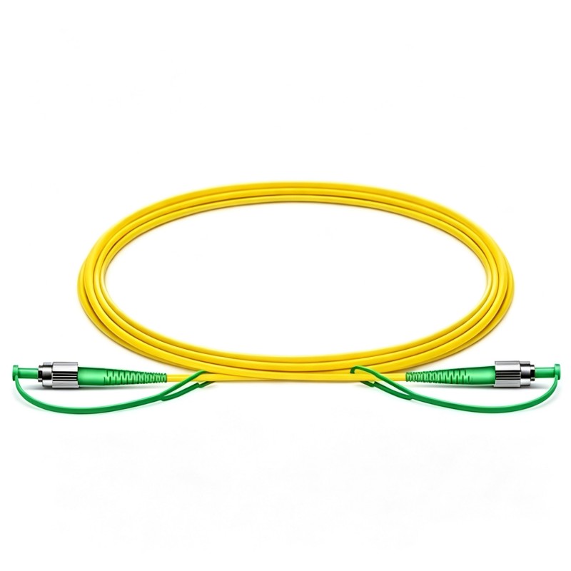
FIRSOL's current PBS/PBC product configurations support 250 µm bare fiber or 900 µm loose-tube pigtails, multiple pigtail lengths, and connector options including LC, SC, FC, and ST with UPC or APC configurations depending on the selected product.
Frequently Asked Questions About Polarization Beam Combiners/Splitters
Can the same device work as both a PBS and a PBC?
In many fiber-based designs, yes. A reciprocal PBS/PBC can separate orthogonal polarization states when light propagates from the common port toward the two PM ports and combine them when propagation is reversed.
Is a polarization beam splitter the same as a 1x2 fiber splitter?
No. A conventional 1x2 splitter divides optical power according to a specified coupling ratio. A polarization beam splitter separates light according to polarization state.
Does a polarization beam combiner amplify optical power?
No. A PBC is a passive component. It can combine optical power from two appropriately polarized input signals into one common optical path, but it does not provide optical gain.
Why are Ports 1 and 2 usually PM fiber?
The two ports carry defined orthogonal polarization states. PM fiber helps maintain the required polarization orientation between the external optical system and the polarization-selective element inside the device.
Can the common port also use PM fiber?
Yes. Both SM common-port and all-PM configurations are available. The correct choice depends on whether the downstream optical system needs to preserve a defined polarization-axis relationship.
What does “slow axis aligned to the connector key” mean?
It means the slow axis of the PM fiber has a defined mechanical orientation relative to the connector key. This allows two PM fiber components to be connected with predictable axis alignment rather than an unknown rotational orientation.
Is a higher extinction ratio always better?
A higher extinction ratio generally provides better separation between orthogonal polarization states. However, system performance also depends on insertion loss, source polarization quality, fiber-axis alignment, splices, connectors, wavelength, temperature, and other components in the optical path.
Should I choose UPC or APC connectors?
The choice depends on system requirements. APC connectors are commonly considered where lower back reflection is important, while UPC connectors may be sufficient in systems that are less sensitive to reflected light. The complete system specification should determine the connector type rather than the PBS/PBC alone.
Conclusion
A Polarization Beam Splitter/Combiner (PBS/PBC) is a specialized fiber optic component used to separate or combine orthogonal polarization states. Its function is fundamentally different from an ordinary optical power splitter because the routing of light depends on polarization rather than a fixed power-splitting ratio.
When selecting a PBS/PBC, engineers should consider the operating wavelength, insertion loss, extinction ratio, return loss, directivity, optical power, PM fiber configuration, axis orientation, pigtail construction, and connector requirements as part of the complete optical system.
For applications that require an SM common port, an all-PM configuration, different PM-axis relationships, specific wavelengths, higher optical power, or connectorized assemblies, these requirements should be defined before ordering.
FIRSOL provides 1x2 Polarization Beam Combiner/Splitter solutions across visible, near-infrared, laser, and telecom wavelength ranges, with configurable PM/SM fiber structures, optical power levels, pigtail lengths, fiber coatings, and connector options for fiber lasers, optical amplifiers, coherent communication, optical sensing, and polarization-sensitive fiber systems.