What Is a C-Lens Fiber Collimator? Working Principle, Specifications, and Selection Guide
Fiber-based optical systems do not always keep light inside an optical fiber throughout the entire optical path. In many applications, the guided optical signal must leave the fiber, travel through a free-space optical section, interact with one or more optical components, and then be coupled back into another fiber.
A bare single-mode fiber cannot perform this transition efficiently by itself. Once light exits the fiber core, the beam begins to diverge. A fiber collimator is therefore used to transform the divergent fiber output into a controlled, low-divergence free-space beam.
Among the different micro-optic solutions available, the C-lens fiber collimator is widely used in compact optical communication components, fiber laser systems, fiber amplifiers, sensors, and LiDAR assemblies. Its small package, fixed optical alignment, and configurable working distance make it particularly suitable for integration into miniature optical systems.
What Is a C-Lens Fiber Collimator?
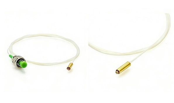
A C-lens fiber collimator is a compact optical assembly that typically combines:
A single-mode optical fiber
A fiber ferrule or capillary
A precision C-lens
A protective glass or metal tube
A fixed fiber-to-lens alignment structure
Its primary function is to convert the divergent output from a single-mode fiber into a low-divergence free-space beam. Because optical propagation is reciprocal, the same device can also collect an incoming free-space beam and focus it into the core of a single-mode fiber.
The Firsol Single Mode C-Lens Fiber Collimator is designed for both fiber-to-free-space collimation and free-space-to-fiber coupling, with fixed optical alignment intended to provide stable beam quality, low insertion loss, and long-term reliability.
A fiber collimator can therefore be considered an optical interface between two different propagation environments:
Guided light in fiber → Free-space optical beamor, in the reverse direction:
Free-space optical beam → Guided light in fiberIt is important to note that a real optical beam is not perfectly parallel. Even a properly collimated Gaussian beam retains a finite amount of diffraction-related divergence. In practical engineering, “collimated” means that the beam expands slowly enough over the required propagation distance to meet the system’s optical performance requirements. Single-mode fiber output is commonly treated as a near-Gaussian beam for collimator design and characterization.
How Does a C-Lens Fiber Collimator Work?
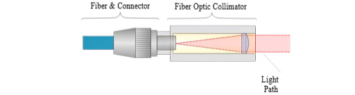
Light propagating through a single-mode fiber is confined to a small optical mode inside the fiber core. When the light reaches the fiber end face, that confinement ends and the beam begins to expand.
The C-lens is positioned at a precisely controlled distance from the fiber end. This spacing allows the lens to reshape the diverging optical wavefront and produce a beam with the required diameter, divergence, and working distance.
The process can be divided into four stages.
1. Light exits the single-mode fiber
The guided optical mode leaves the fiber end face and begins to diverge. The amount of divergence depends primarily on the operating wavelength and the mode field characteristics of the selected fiber.
Fibers with smaller mode field diameters or higher numerical apertures generally produce more rapidly diverging output beams, which places greater demands on lens design and alignment.
2. The divergent beam enters the C-lens
The expanding beam reaches the C-lens. The lens refracts different portions of the optical wavefront so that the output beam has substantially lower divergence.
The fiber position, lens geometry, optical coating, and distance between the fiber and lens must be optimized as a complete system. Small lateral or axial alignment errors can change beam pointing, introduce aberrations, and increase coupling loss. Research on fiber collimator assemblies shows that both transverse centering and axial fiber-to-lens spacing are critical to controlling beam shape and pointing stability.
3. The beam propagates through free space
After leaving the lens, the beam travels through a defined free-space section. This section may contain:
An optical filter
An isolator crystal
A polarizer
A mirror
A beam splitter
A photodetector
A sensing element
Another fiber collimator
Fiber collimators are commonly incorporated into systems in which free-space optical elements are placed between input and output fibers. Patented fiber-collimator designs describe their use with filters, mirrors, detectors, Bragg gratings, additional lenses, and second collimators.
4. Light is coupled into a receiving fiber
In a two-collimator arrangement, the receiving C-lens focuses the incoming beam toward the second fiber core.
Efficient coupling requires the focused optical field to match the position, angle, and mode characteristics of the receiving fiber. Lateral displacement, angular error, incorrect spacing, or optical contamination can significantly reduce coupling efficiency.
What Is the Working Distance of a Fiber Collimator?
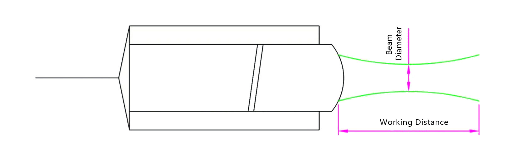
Working distance is one of the most important specifications for a C-lens fiber collimator.
In a matched collimator pair, it generally describes the designed free-space separation between the facing optical assemblies at which the specified coupling performance is achieved. The exact mechanical reference points used to define working distance should always be confirmed from the product drawing.
A short working distance is useful when:
The optical system must be extremely compact
Only a thin filter or optical element is inserted
Minimum package length is required
Environmental stability is more important than free-space clearance
A longer working distance is useful when:
Several optical elements must be placed in the beam path
The system requires additional mechanical clearance
A mirror, filter, crystal, or sensing target must be inserted
Direct physical contact between assemblies must be avoided
A longer working distance is not automatically better. Increasing the propagation distance can increase sensitivity to beam divergence, angular alignment, mechanical tolerances, and environmental drift. The working distance should therefore be selected according to the actual optical layout rather than maximized without a system-level reason.
Firsol provides working-distance options of 5 mm, 50 mm, and, for applicable wavelength configurations, 100 mm.
Key Specifications of a C-Lens Fiber Collimator
A C-lens collimator should not be selected using wavelength alone. The following parameters must be evaluated together.
Parameter | What It Describes | Why It Matters |
|---|---|---|
Center Wavelength | Nominal design wavelength | Determines lens optimization, coating performance, fiber selection, and beam behavior |
Operating Wavelength Range | Permitted wavelength variation around the center wavelength | Important for tunable sources, broadband signals, and wavelength drift |
Working Distance | Designed free-space propagation distance | Determines component spacing and mechanical layout |
Beam Diameter | Diameter of the collimated beam | Affects optical aperture requirements and interaction with filters or other components |
Insertion Loss | Optical power lost through the collimator or matched pair | Directly affects system power budget |
Return Loss | Amount of light reflected toward the source | Important for lasers and reflection-sensitive optical systems |
Polarization-Dependent Loss | Loss variation with input polarization | Important in polarization-sensitive systems |
Maximum Optical Power | Maximum supported continuous-wave input | Prevents thermal or optical damage |
Fiber Type | Fiber used in the pigtail assembly | Must match wavelength, mode field, numerical aperture, and system requirements |
Package Dimensions | Mechanical size of the optical assembly | Determines integration compatibility |
Operating Temperature | Qualified environmental range | Important for industrial and field-deployed systems |
Center wavelength and operating range
The C-lens, fiber, and optical coatings are normally optimized for a defined wavelength region. Operating far from the design wavelength may change:
Effective focal behavior
Beam diameter
Beam divergence
Insertion loss
Return loss
Coupling efficiency
A collimator designed for 1550 nm should therefore not be assumed to provide the same performance at 1064 nm or 2000 nm.
Firsol’s available center-wavelength configurations cover visible, near-infrared, telecom, and approximately 2 µm bands, including:
532 nm
630/670 nm
780/830/850 nm
980/1030/1064 nm
1310/1480/1550 nm
1950/2000/2050 nm
The specified operating range is ±10 nm for selected visible-wavelength versions and ±30 nm for the other listed wavelength groups.
Insertion loss
Insertion loss measures the reduction in optical power caused by the complete optical path under the specified test conditions.
Loss may result from:
Fresnel reflections
Lens aberrations
Fiber-to-lens misalignment
Beam clipping
Angular pointing error
Mode mismatch
Connector loss
Contamination
Incorrect working distance
In a matched pair, the total measured loss typically includes both collimators and the free-space coupling between them. The test configuration should therefore be confirmed when comparing specifications from different suppliers.
Lens aberration and mode mismatch can become especially significant when small-core, high-numerical-aperture fibers are used. Optical collimator research and patented designs show that marginal rays, spherical aberration, and mismatched focused spot sizes can increase coupling loss.
Return loss
Return loss describes how much optical power is reflected back toward the source. A higher positive return-loss value indicates lower reflected power.
High return loss is particularly important for:
Narrow-linewidth lasers
Fiber lasers
Optical amplifiers
Coherent communication systems
Interferometric sensors
Reflection-sensitive test equipment
Angled optical interfaces and anti-reflection coatings are commonly used in fiber collimator assemblies to reduce Fresnel reflections and improve coupling performance.
Firsol specifies a minimum return loss of 50 dB for the bare collimator configuration. The specification notes that adding connectors may reduce return loss by approximately 5 dB.
Beam diameter and divergence
Beam diameter determines the size of the optical footprint at the output of the collimator.
A larger beam may provide lower diffraction-related divergence, but it also requires:
Larger optical elements
Larger clear apertures
More package space
Tighter control of beam clipping
A smaller beam supports compact optical assemblies, but it may diverge more rapidly and can produce higher optical intensity on small surfaces.
Beam diameter must not be confused with fiber core diameter or mode field diameter. The fiber mode may be only several micrometers wide, while the C-lens expands it into a free-space beam hundreds of micrometers in diameter.
The Firsol Single Mode C-Lens Fiber Collimator specifies a beam diameter of no more than 0.6 mm under the stated test conditions.
Polarization-dependent loss
Polarization-dependent loss, or PDL, is the variation in insertion loss as the polarization state of the input light changes.
Low PDL is important when:
The source polarization is not controlled
The polarization changes during operation
The system contains polarization-sensitive components
Stable optical power is required regardless of polarization state
Firsol specifies PDL of no more than 0.2 dB for this single-mode C-lens collimator series.
Maximum optical power
The permitted optical power depends on more than the nominal rating of the fiber itself. Optical power density may be concentrated at:
The fiber end face
Adhesive interfaces
Lens surfaces
Coating layers
Contaminated areas
Visible and short-wavelength systems may have different limits from telecom or near-infrared systems. The exact wavelength, fiber type, package structure, cleanliness requirements, and connector configuration should be confirmed for high-power use.
Firsol specifies 0.1 W for the 532 nm configuration and provides 0.5 W, 1 W, 5 W, and 10 W options for applicable wavelength and fiber combinations.
C-Lens Collimators Compared with GRIN and Aspheric Collimators
C-lenses, GRIN lenses, and aspheric lenses can all be used for fiber collimation. None is universally superior; the appropriate solution depends on the optical and mechanical requirements.
Lens Type | General Characteristics | Typical Considerations |
|---|---|---|
C-Lens | Compact micro-optic, fixed alignment, configurable working distance | Well suited to miniature passive components and matched-pair assemblies |
GRIN Lens | Uses a refractive-index gradient rather than only surface curvature | Compact, but performance depends strongly on lens pitch, wavelength, and assembly design |
Aspheric Lens | Uses a non-spherical surface to control aberrations | Can support high-quality collimation and larger beam sizes, but may require a larger or more complex package |
C-lenses are often selected when a compact, permanently aligned pigtail assembly is required. Aspheric collimators may be preferred when a larger output beam, adjustable focus, or specific aberration control is needed. GRIN lenses remain common in miniature passive optical components where their dimensions and pitch characteristics match the required optical path.
The final performance depends on the complete assembly—not simply on the lens category. Fiber mode field, focal properties, optical coating, alignment, package stability, and operating wavelength must all be considered. For a more detailed comparison, please read our related article, “Fiber Collimator vs. GRIN Lens: Key Differences, Limitations, and How to Choose.”
Typical Applications
Fiber lasers
A C-lens collimator can transfer light between a fiber laser and free-space components such as isolators, mirrors, filters, modulators, and diagnostic equipment.
For higher-power systems, the selected fiber, lens coating, connector condition, and optical cleanliness must all be verified against the actual continuous-wave or pulsed operating conditions.
Fiber amplifiers
Fiber amplifiers may require free-space access for filters, polarization-control components, pump-management optics, or monitoring devices.
Low insertion loss is important because unnecessary loss reduces available output power and can affect the overall amplifier power budget.
Optical communication components
C-lens collimators are widely integrated into compact free-space optical assemblies such as:
Optical isolators
Optical circulators
Wavelength filters
WDM devices
Optical switches
Variable optical attenuators
Monitoring modules
In these devices, one collimator launches the signal into the free-space optical section and another collimator returns the processed signal to fiber.
LiDAR and optical ranging
Fiber collimators can provide a compact interface between a fiber-coupled laser source and the transmit or receive optics of a LiDAR system.
The required beam diameter, divergence, wavelength, power, and environmental stability should be determined from the complete ranging architecture rather than from the collimator alone.
Fiber-optic sensing
Collimators may be used to direct light toward:
Reflective targets
Gas cells
Interferometric elements
Free-space sensing surfaces
Spectroscopic samples
The return signal can then be collected by the same collimator or by a separate receiving collimator, depending on the optical layout.
The Firsol specification identifies fiber lasers, fiber amplifiers, optical communication systems, and LiDAR as principal application areas.
How to Select the Right C-Lens Fiber Collimator
1. Identify the exact operating wavelength
Select the version designed for the actual laser or signal wavelength. For tunable sources, confirm that the complete tuning range remains inside the specified operating range.
2. Match the fiber type
The fiber must be suitable for the wavelength and optical mode of the system. Firsol uses wavelength-appropriate fibers including 460-HP, 630-HP, 780-HP, Hi1060, SMF-28e, and SM1950.
A generic “single-mode fiber” designation is not sufficient for precise collimator selection because mode field diameter and numerical aperture vary among fiber types.
3. Determine the required working distance
Create a mechanical drawing of the free-space optical section and calculate the actual distance needed between collimators or optical reference surfaces.
Do not select a longer working distance simply because it appears more flexible. Use the shortest distance that provides sufficient clearance for the intended optical elements and mechanical tolerances.
4. Check beam diameter and optical aperture
Verify that every filter, mirror, aperture, crystal, and detector in the free-space section has sufficient clear aperture for the beam.
Additional allowance should be provided for:
Beam divergence
Mechanical tolerances
Alignment errors
Temperature-related movement
Edge clearance
5. Establish the optical loss budget
Determine the maximum acceptable loss for the complete system. The budget should include:
Both collimators
Fiber connectors
Splices
Free-space optical elements
Coating losses
Alignment tolerance
Environmental margin
For Firsol configurations, maximum insertion loss varies with wavelength, ranging from 0.4 dB for the 1310/1480/1550 nm group to 1.6 dB for the 532 nm version under the specified test conditions.
6. Decide between a single unit and a matched pair
A single collimator may be appropriate when coupling to:
A detector
A mirror
A laser source
An existing free-space optical system
A separately aligned receiving assembly
A matched pair is generally preferable when the objective is fiber-to-fiber transmission across a fixed free-space gap. Pair matching reduces uncertainty associated with focal behavior, beam pointing, and coupling compatibility.
Firsol’s ordering structure supports both single collimators and matched pairs, along with selectable wavelengths, working distances, tube types, fiber types, pigtail lengths, cable diameters, and connector terminations.
Installation and Handling Considerations
Even a correctly specified collimator can perform poorly if it is installed or handled incorrectly.
Keep optical surfaces clean
Dust, oil, adhesive residue, and other contaminants can increase loss, scatter light, create unstable measurements, and cause localized heating in higher-power systems.
Use appropriate optical-cleaning procedures and avoid touching exposed lens surfaces.
Maintain the specified spacing
Changing the distance between a matched pair can alter beam size at the receiving lens and reduce coupling efficiency. Mechanical mounts should maintain the specified axial position under vibration and temperature changes.
Control angular alignment
A small angular error can produce a large lateral displacement after the beam propagates across the free-space gap. This effect becomes more significant as working distance increases.
Avoid excessive fiber stress
Firsol specifies a maximum tensile load of 5 N. The fiber pigtail should be strain-relieved and routed without tight bends or mechanical loading near the collimator package.
Account for connector performance
The Firsol specifications are stated excluding connectors. When connectors are added, insertion loss can vary with wavelength, and return loss may decrease by approximately 5 dB. Connectorized and bare-fiber configurations should therefore not be assumed to have identical optical performance.
Firsol Single Mode C-Lens Fiber Collimator Overview
The Firsol Single Mode C-Lens Fiber Collimator series provides configurable solutions across wavelengths from 532 nm to 2050 nm.
Key available specifications include:
Specification | Available Performance |
|---|---|
Center Wavelengths | 532 to 2050 nm |
Operating Range | ±10 nm or ±30 nm, depending on wavelength |
Working Distance | 5 mm, 50 mm, or 100 mm where applicable |
Beam Diameter | ≤0.6 mm |
Maximum Insertion Loss | 0.4 to 1.6 dB, depending on wavelength |
Minimum Return Loss | 50 dB without connectors |
Polarization-Dependent Loss | ≤0.2 dB |
Maximum CW Power | Up to 10 W for applicable configurations |
Package Options | Φ3.2 × 10 mm gold-plated tube or Φ2.8 × 9 mm glass tube |
Operating Temperature | −5 to +70 °C |
Storage Temperature | −40 to +85 °C |
These specifications are taken from the current Firsol product datasheet and should be confirmed for the final wavelength, working distance, fiber, power, and connector combination before ordering.
Frequently Asked Questions
Is the output of a fiber collimator perfectly parallel?
No. A physical optical beam always has some finite divergence. A properly designed collimator minimizes the divergence sufficiently for the specified working distance and optical system.
Can the same C-lens collimator be used at different wavelengths?
Only within its qualified operating range. Changing wavelength affects the fiber mode, lens focal behavior, coating response, beam diameter, and coupling efficiency.
Does a longer working distance always provide better performance?
No. A longer working distance provides more mechanical clearance but can increase sensitivity to beam divergence, pointing error, vibration, and alignment tolerances.
Is beam diameter the same as the fiber core diameter?
No. The optical mode inside a single-mode fiber is typically only several micrometers wide. The collimator expands that mode into a much larger free-space beam.
Should two separately purchased collimators be used as a pair?
They may work together when their optical parameters are compatible, but a factory-matched pair is preferable when low coupling loss and predictable working distance are important.
Can connectors affect collimator performance?
Yes. Connectors introduce additional interfaces and alignment tolerances. Depending on connector type, wavelength, and termination quality, they may increase insertion loss and reduce return loss.
Conclusion
A C-lens fiber collimator is a compact and precise interface between single-mode fiber transmission and free-space optical propagation. It can convert the divergent output of an optical fiber into a controlled beam or couple a free-space beam back into the fiber.
Successful selection requires more than choosing the correct wavelength. Working distance, beam diameter, fiber type, insertion loss, return loss, polarization-dependent loss, power handling, and mechanical configuration must all be considered as part of the complete optical system.
For applications requiring specific wavelengths, custom working distances, higher optical power, matched collimator pairs, or customized pigtails and connectors, the complete operating conditions should be provided before the collimator design is finalized.